USD 75.92 – USD 137.28Price range: USD 75.92 through USD 137.28
| Operating modes | Supply voltage | Control output | H3DT-H | ||
|---|---|---|---|---|---|
| S Series (time range: 0.1 to 12 s) |
L Series (time range: 1.0 to 120 s) |
||||
| Power OFF Delay | 100 to 120 VAC | Contact output: SPDT | Model | H3DT-HCS | H3DT-HCL |
| 200 to 240 VAC | Contact output: SPDT | H3DT-HDS | H3DT-HDL | ||
| 24 to 48 VAC/DC | Contact output: SPDT | H3DT-HBS | H3DT-HBL | ||
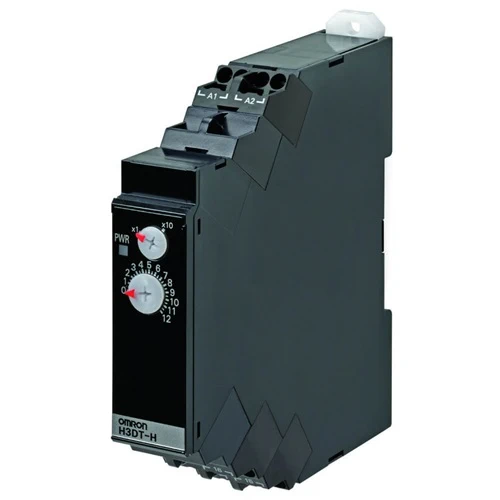
| Model | Terminal block | Operating/resetting method | Output type | Mounting method | Safety standards |
|---|---|---|---|---|---|
| H3DT-H | 6 terminals | Instantaneous operation/ time-limit reset |
Relay, SPDT | DIN Track mounting | cULus (UL 508 CSA C22.2 No. 14) CCC LR EN 61812-1 IEC 60664-1 4 kV/2 |
| S Series | L Series | |||
|---|---|---|---|---|
| Time range setting | x0.1 | x1 | x1 | x10 |
| Set time range | 0.1 to 1.2 s | 1 to 12 s | 1 to 12 s | 10 to 120 s |
| Power ON time | 0.1 s min. | 0.3 s min. | ||
| Scale numbers | 12 | |||
| upply voltage | H3DT-HCS/-HCL | 100 to 120 VAC, 50/60 Hz |
|---|---|---|
| H3DT-HDS/-HDL | 200 to 240 VAC, 50/60 Hz | |
| H3DT-HBS/-HBL | 24 to 48 VAC/DC, 50/60 Hz *1 | |
| Allowable voltage fluctuation range | 85% to 110% of rated voltage | |
| Power consumption | H3DT-HCS | At 120 VAC: 8.7 VA max. |
| H3DT-HCL | At 120 VAC: 8.8 VA max. | |
| H3DT-HDS | At 240 VAC: 21.6 VA max. | |
| H3DT-HDL | At 240 VAC: 21.7 VA max. | |
| H3DT-HBS/-HBL | At 48 VAC: 1.0 VA max., at 24 VDC: 0.4 W max. | |
| Timer operation starting voltage | 30% or less of power supply voltage | |
| Rated Insulation Voltage | 250 VAC | |
| Control output | Contact output, 5 A at 250 VAC with resistive load (cosφ = 1), 5 A at 30 VDC with resistive load Contact materials: Ag-alloy (Recommended fuse: BLN5 (Littelfuse) or 0216005MXEP) |
|
| Ambient operating temperature | -20 to 60°C (with no icing) | |
| Storage temperature | -40 to 70°C (with no icing) | |
| Surrounding air operating humidity | 25% to 85% | |
* DC ripple: 20% max.
| Accuracy of operating time | ±1% of FS max. (±1% ±10 ms max. at 1.2-s range) | |
|---|---|---|
| Setting error | ±10% of FS ±0.05 s max. | |
| Influence of voltage | ±0.5% of FS max. (±0.5% ±10 ms max. at 1.2-s range) | |
| Influence of temperature | ±2% of FS max. (±2% ±10 ms max. at 1.2-s range) | |
| Insulation resistance | 100 MΩ min. at 500 VDC | |
| Dielectric strength | Between charged metal part and operating section: 2,900 VAC 50/60 Hz for 1 min. Between control output terminals and operating circuit: 2,000 VAC 50/60 Hz for 1 min. Between contacts not located next to each other: 1,000 VAC 50/60 Hz for 1 min. |
|
| Impulse withstand test voltage |
Between power supply terminals: 1 kV for 24-VAC/DC and 48-VAC/DC models, 5 kV for all other models. Between conductor terminal and operating section: 7.4 kV |
|
| Noise immunity | Square-wave noise generated by noise simulator (pulse width: 100 ns/1 μs, 1-ns rise): ±1.5 kV (between power supply terminals) |
|
| Static immunity | Malfunction: 4 kV, Destruction: 8 kV | |
| Vibration resistance |
Destruction | 0.75-mm single amplitude at 10 to 55 Hz for 2 h each in 3 directions |
| Malfunction | 0.5-mm single amplitude at 10 to 55 Hz for 10 min each in 3 directions | |
| Shock resistance |
Destruction | 1,000 m/s2 3 times each in 6 directions |
| Malfunction | 100 m/s2 3 times each in 6 directions | |
| Life expectancy |
Mechanical | 10 million operations min. (under no load at 1,800 operations/h) |
| Electrical | 100,000 operations min. (5 A at 250 VAC, resistive load at 360 operations/h) | |
| Degree of protection | IP30 (Terminal block: IP20) | |
| Weight | Approx. 90 g | |