USD 104.52 – USD 200.72Price range: USD 104.52 through USD 200.72
Scalable and cost-optimized configuration of a ET 200SP station is achieved by a comprehensive portfolio of digital and analog IO modules.
SIMATIC ET 200SP is about 50% narrower than other distributed peripheries. With its height of 115 millimeters, the system can accommodate 16 channels with single-wire connection (without AUX-plugs). For a 3-wire connection with AUX-plugs the height for 8 channels is 140 millimeters. The depth is 75 millimeters. In order to keep its small size, the power module for load group formation is integrated into the system of SIMATIC ET 200SP.
The peripheral modules are labelled with different colored squares to identify easily the type of module.
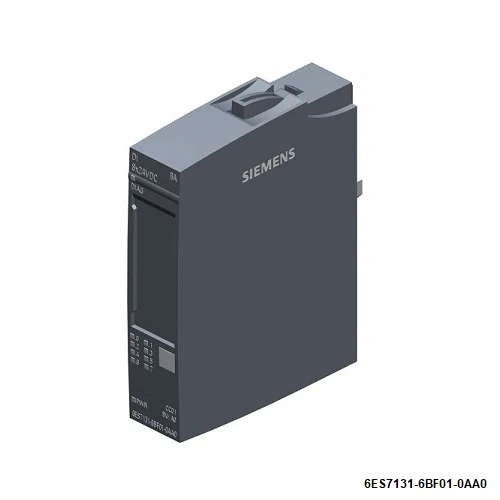
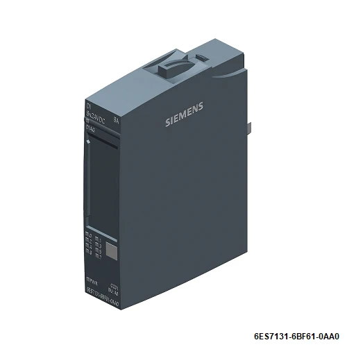
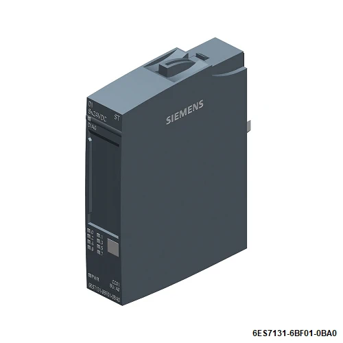
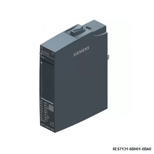
| Article number | 6ES7131-6BF01-0AA0 | 6ES7131-6BF61-0AA0 | 6ES7131-6BF01-0BA0 | 6ES7131-6BH01-0BA0 |
| ET 200SP, DI 8x 24V DC Basic, PU 1 | ET 200SP, DI 8x 24V DC SRC BA | ET 200SP, DI 8x 24V DC ST, PU 1 | ET 200SP, DI 16x 24V DC ST, PU 1 | |
| General information | ||||
| Product type designation | DI 8x24VDC BA | DI 8×24 VDC SRC BA | DI 8×24 VDC ST | DI 16x24VDC ST |
| HW functional status | FS03 | From FS02 | From FS02 | From FS02 |
| Firmware version | V0.0 | V0.0 | V0.0 | V0.0 |
| ● FW update possible | No | No | No | No |
| usable BaseUnits | BU type A0 | BU type A0 | BU type A0 | BU type A0 |
| Color code for module-specific color identification plate | CC01 | CC02 | CC01 | CC00 |
| Product function | ||||
| ● I&M data | Yes; I&M0 to I&M3 | Yes; I&M0 to I&M3 | Yes; I&M0 to I&M3 | Yes; I&M0 to I&M3 |
| ● Isochronous mode | No | No | No | No |
| Engineering with | ||||
| ● STEP 7 TIA Portal configurable/integrated from version | V14 | V14 | V14 | V14 |
| ● STEP 7 configurable/integrated from version | V5.5 SP3 / – | V5.5 SP3 / – | V5.5 SP3 or higher | V5.5 SP3 |
| ● PCS 7 configurable/integrated from version | V8.1 SP1 | V8.1 SP1 | ||
| ● PROFIBUS from GSD version/GSD revision | One GSD file each, Revision 3 and 5 and higher | One GSD file each, Revision 3 and 5 and higher | One GSD file each, Revision 3 and 5 and higher | One GSD file each, Revision 3 and 5 and higher |
| ● PROFINET from GSD version/GSD revision | GSDML V2.3 | GSDML V2.3 | GSDML V2.3 | GSDML V2.3 |
| Operating mode | ||||
| ● DI | Yes | Yes | Yes | Yes |
| ● Counter | No | No | No | No |
| ● Oversampling | No | No | No | No |
| ● MSI | No | No | No | No |
| Supply voltage | ||||
| Rated value (DC) | 24 V | 24 V | 24 V | 24 V |
| permissible range, lower limit (DC) | 19.2 V | 19.2 V | 19.2 V | 19.2 V |
| permissible range, upper limit (DC) | 28.8 V | 28.8 V | 28.8 V | 28.8 V |
| Reverse polarity protection | Yes | Yes | Yes | Yes |
| Input current | ||||
| Current consumption, max. | 70 mA; All channels are supplied from the encoder supply | 50 mA; All channels are supplied from the encoder supply | 90 mA | |
| Encoder supply | ||||
| Number of outputs | 8 | 8 | ||
| Output voltage, min. | 19.2 V | 19.2 V | ||
| Short-circuit protection | Yes; per module | No | Yes; per module | |
| 24 V encoder supply | ||||
| ● 24 V | Yes | Yes | No | |
| ● Short-circuit protection | Yes | Yes | ||
| ● Output current, max. | 700 mA | |||
| ● Output current per channel, max. | 700 mA | 700 mA | ||
| ● Output current per module, max. | 700 mA | 700 mA | ||
| Power loss | ||||
| Power loss, typ. | 1.6 W; 24 V, 8 inputs supplied via encoder supply | 1.5 W | 1 W; 24 V, 8 inputs supplied via encoder supply | 1.7 W |
| Address area | ||||
| Address space per module | ||||
| ● Inputs | 1 byte | 1 byte | 1 byte; + 1 byte for QI information | 2 byte; + 2 bytes for QI information |
| Hardware configuration | ||||
| Automatic encoding | Yes | Yes | Yes | Yes |
| ● Mechanical coding element | Yes | Yes | Yes | |
| ● Type of mechanical coding element | Type A | type B | Type A | Type A |
| Selection of BaseUnit for connection variants | ||||
| ● 1-wire connection | BU type A0 | BU type A0 | BU type A0 | BU type A0 |
| ● 2-wire connection | BU type A0 | BU type A0 | BU type A0 | BU type A0 + Potential distributor module |
| ● 3-wire connection | BU type A0 with AUX terminals or potential distributor module | BU type A0 with AUX terminals or potential distributor module | BU type A0 with AUX terminals or potential distributor module | BU type A0 + Potential distributor module |
| ● 4-wire connection | BU type A0 + Potential distributor module | BU type A0 + Potential distributor module | BU type A0 + Potential distributor module | BU type A0 + Potential distributor module |
| Digital inputs | ||||
| Number of digital inputs | 8 | 8 | 8 | 16 |
| Digital inputs, parameterizable | Yes | Yes | Yes | Yes |
| Source/sink input | P-reading | Sourcing | P-reading | P-reading |
| Input characteristic curve in accordance with IEC 61131, type 1 | Yes | Yes | ||
| Input characteristic curve in accordance with IEC 61131, type 2 | Yes | |||
| Input characteristic curve in accordance with IEC 61131, type 3 | Yes | Yes | Yes | |
| Input voltage | ||||
| ● Rated value (DC) | 24 V | 24 V | 24 V | 24 V |
| ● for signal “0” | -30 to +5 V | 30 V to -5 V (reference potential is L+) | -30 to +5 V | -30 to +5 V |
| ● for signal “1” | +11 to +30V | -11 V to -30 V (reference potential is L+) | +11 to +30V | +11 to +30V |
| Input current | ||||
| ● for signal “1”, typ. | 6.8 mA | 6 mA | 2.5 mA | 2.5 mA |
| Input delay (for rated value of input voltage) | ||||
| for standard inputs | ||||
| — parameterizable | Yes; 0.05 / 0.1 / 0.4 / 0.8 / 1.6 / 3.2 / 12.8 / 20 ms (in each case + delay of 30 to 500 µs, depending on line length) | Yes; 0.05 / 0.1 / 0.4 / 0.8 / 1.6 / 3.2 / 12.8 / 20 ms (in each case + delay of 30 to 500 µs, depending on line length) | Yes; 0.05 / 0.1 / 0.4 / 0.8 / 1.6 / 3.2 / 12.8 / 20 ms (in each case + delay of 30 to 500 µs, depending on line length) | Yes; 0.05 / 0.1 / 0.4 / 0.8 / 1.6 / 3.2 / 12.8 / 20 ms (in each case + delay of 30 to 500 µs, depending on line length) |
| — at “0” to “1”, min. | 0.05 ms | 0.05 ms | 0.05 ms | 0.05 ms |
| — at “0” to “1”, max. | 20 ms | 20 ms | 20 ms | 20 ms |
| — at “1” to “0”, min. | 0.05 ms | 0.05 ms | 0.05 ms | 0.05 ms |
| — at “1” to “0”, max. | 20 ms | 20 ms | 20 ms | 20 ms |
| Cable length | ||||
| ● shielded, max. | 1 000 m | 1 000 m | 1 000 m | 1 000 m |
| ● unshielded, max. | 600 m | 200 m | 600 m | 600 m |
| Encoder | ||||
| Connectable encoders | ||||
| ● 2-wire sensor | Yes | Yes | Yes | Yes |
| — permissible quiescent current (2-wire sensor), max. | 2 mA | 1.5 mA | 1.5 mA | 1.5 mA |
| Interrupts/diagnostics/status information | ||||
| Diagnostics function | Yes | Yes | Yes | Yes |
| Alarms | ||||
| ● Diagnostic alarm | Yes | Yes | Yes | Yes |
| Diagnoses | ||||
| ● Diagnostic information readable | Yes | Yes | Yes | Yes |
| ● Monitoring the supply voltage | Yes | Yes | Yes | Yes |
| — parameterizable | Yes | Yes | Yes | Yes |
| ● Monitoring of encoder power supply | No | No | Yes; Module-by-module, optional protective circuit for preventing wire-break diagnostics in the case of simple encoder contacts: 25 kOhm to 45 kOhm | No |
| ● Wire-break | No | No | Yes; Module-wise | Yes; Module-by-module, optional protective circuit for preventing wire-break diagnostics in the case of simple encoder contacts: 25 kOhm to 45 kOhm |
| ● Short-circuit | No | No | Yes; Module-wise | No |
| ● Group error | Yes | Yes | ||
| Diagnostics indication LED | ||||
| ● Monitoring of the supply voltage (PWR-LED) | Yes; green PWR LED | Yes; green PWR LED | Yes; green PWR LED | Yes; green PWR LED |
| ● Channel status display | Yes; green LED | Yes; green LED | Yes; green LED | Yes; green LED |
| ● for channel diagnostics | No | No | No | No |
| ● for module diagnostics | Yes; green/red DIAG LED | Yes; green/red DIAG LED | Yes; green/red DIAG LED | Yes; green/red DIAG LED |
| Potential separation | ||||
| Potential separation channels | ||||
| ● between the channels | No | No | No | No |
| ● between the channels and backplane bus | Yes | Yes | Yes | Yes |
| ● between the channels and the power supply of the electronics | No | No | No | No |
| Isolation | ||||
| Isolation tested with | 707 V DC (type test) | 707 V DC (type test) | 707 V DC (type test) | 707 V DC (type test) |
| Standards, approvals, certificates | ||||
| Suitable for safety functions | No | No | No | No |
| Ambient conditions | ||||
| Ambient temperature during operation | ||||
| ● horizontal installation, min. | -30 °C; < 0 °C as of FS03 | -30 °C; < 0 °C as of FS02 | -30 °C; < 0 °C as of FS02 | -30 °C; < 0 °C as of FS02 |
| ● horizontal installation, max. | 60 °C | 60 °C | 60 °C | 60 °C |
| ● vertical installation, min. | -30 °C; < 0 °C as of FS03 | -30 °C; < 0 °C as of FS02 | -30 °C; < 0 °C as of FS02 | -30 °C; < 0 °C as of FS02 |
| ● vertical installation, max. | 50 °C | 50 °C | 50 °C | 50 °C |
| Altitude during operation relating to sea level | ||||
| ● Installation altitude above sea level, max. | 5 000 m; Restrictions for installation altitudes > 2 000 m, see manual | 5 000 m; Restrictions for installation altitudes > 2 000 m, see manual | 5 000 m; Restrictions for installation altitudes > 2 000 m, see manual | 5 000 m; Restrictions for installation altitudes > 2 000 m, see manual |
| Dimensions | ||||
| Width | 15 mm | 15 mm | 15 mm | 15 mm |
| Height | 73 mm | 73 mm | 73 mm | 73 mm |
| Depth | 58 mm | 58 mm | 58 mm | 58 mm |
| Weights | ||||
| Weight, approx. | 28 g | 28 g | 28 g | 28 g |