| Model | Operating modes | Terminal block |
Input type | Output type | Mounting method |
Safety standards |
|---|---|---|---|---|---|---|
| H3DT-N2 | A2: ON Delay (Power ON Delay) B3: Flicker OFF Start (Power ON Start) B4: Flicker ON Start (Power ON Start) D: Signal OFF Delay E2: Interval (Power ON Start) E3: Signal OFF Interval F2: Cumulative (ON Delay) F3: Cumulative (Interval) |
10 terminals | Voltage input |
Relay, DPDT |
DIN Track mounting |
cULus (UL 508 CSA C22.2 No.14) CCC LR EN 61812-1 IEC 60664-1 4 kV/2 |
| H3DT-N1 | 8 terminals | Relay, SPDT |
||||
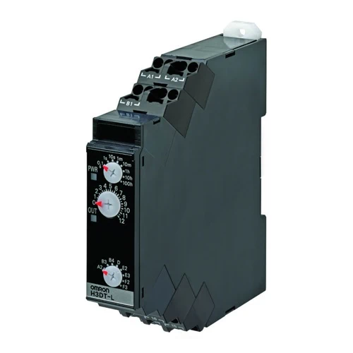
| H3DT-L2 | A: ON Delay (Signal ON Delay) B: Flicker OFF Start (Signal Start) B2: Flicker ON Start (Signal Start) C: Signal ON/OFF Delay E: Interval (Signal Start) G: Signal ON/OFF Delay J: One-shot Output (Signal Start) J2: One-shot Output (Power ON Start) |
10 terminals | Relay, DPDT |
|||
| H3DT-L1 | 8 terminals | Relay, SPDT |