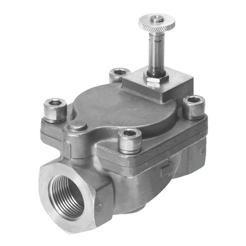
Festo 546165 Media Valve, G3/4, 25 mm, NBR, Coil Separate

USD 476.32

Servo-controlled 2/2 normally closed media valve with stainless-steel body, G3/4 ports, 8.5 m³/h Kv and 0.5 bar required differential; MH coil separate.

Festo Solenoid-Actuated Process and Media Valves

Festo VZWM-L-M22C-G34-F5-R1 Solenoid Media Valve

BrandFesto
Model IdentifierVZWM-L-M22C-G34-F5-R1
Official Part Number546165

Technical Overview

The Festo VZWM-L-M22C-G34-F5-R1 is a servo-controlled diaphragm media valve with G3/4 process connections, 25 mm nominal size and a 2/2-way normally closed function. Its Kv is 8.5 m³/h, and the piloted mechanism requires a 0.5 bar pressure differential. The operating envelope differs by medium: 0.5–6 bar for liquids and 0.5–10 bar for gases, with a separate 5–50 °C liquid-temperature range. Cast stainless steel and NBR seals form the principal housing and sealing materials. The valve uses a separately ordered MH-series solenoid coil and mounts inline, preferably upright; the 1200 g valve body does not establish a supplied coil voltage.

G3/4 servo-controlled normally closed diaphragm valve with 25 mm passage, 8.5 m³/h Kv, NBR seals and separately ordered MH solenoid coil.

Key Features

  • 2/2-way normally closed, servo-controlled diaphragm valve
  • G3/4 process connections and 25 mm nominal passage
  • 8.5 m³/h Kv and 10000 l/min standard nominal flow to DIN 1343
  • 0.5 bar required pressure differential
  • Liquid operating pressure 0.5–6 bar; gaseous-media pressure 0.5–10 bar
  • Liquid-media temperature 5–50 °C; general media and ambient range −10 to 60 °C
  • MH-series solenoid coil ordered separately; no coil voltage assigned to this body
  • Cast-stainless-steel housing, material number 1.4581, with NBR seals
  • Maximum media viscosity 22 mm²/s and non-reversible flow direction
  • 1200 g product weight; inline installation, preferably upright

Switch a G3/4 media line through an 8.5 m³/h Kv diaphragm valve with stainless-steel housing and a separately selected MH coil.

Technical Specification Matrix

ParameterValue
DesignDiaphragm valve; servo-controlled
Type of actuationElectrical
Sealing principleSoft
Mounting positionPreferably upright
Type of mountingInline installation
Connection Process valveG3/4
Electrical connectionSolenoid coil type MH-... , coil can be ordered as an accessory
Nominal size25 mm
Valve function2/2-way, single solenoid, closed
Flow directionNon-reversible
MediumCompressed air to ISO 8573-1:2010 [7:4:4]; Inert gases; Water; Neutral fluids
Medium pressure,valve for liquid media0.05 MPa...0.6 MPa; 0.5 bar...6 bar; 7.25 psi...87 psi
Medium pressure,valve for gaseous media0.05 MPa...1 MPa; 0.5 bar...10 bar; 7.25 psi...145 psi
Burst pressure4 MPa; 40 bar; 580 psi
Overload pressure3.5 MPa; 35 bar; 507.5 psi
Pressure difference0.05 MPa; 0.5 bar; 7.25 psi
Type of pilotingPiloted
Max. viscosity22 mm²/s
Media temperature-10 °C...60 °C
Media temperature for fluids5 °C...50 °C
Ambient temperature-10 °C...60 °C
Flow rate Kv8.5 m³/h
Standard nominal flow rate (standardised to DIN 1343)10000 l/min
Switching time on15 ms
Switch-on time for fluids420 ms
Switching time off12 ms
Switch-off time for fluids950 ms
b value0.5
C value39 l/sbar
Note on materialsRoHS compliant
LABS (PWIS) conformityVDMA24364 zone III
Material housingCast stainless steel
Material number housing1,4581
Material sealsNBR
Material plunger tubeHigh-alloy steel
Physical Weight (kg)1.2
CE mark (see declaration of conformity)In accordance with EU Pressure Equipment Directive
UKCA marking (see declaration of conformity)to UK Pressure Equipment Regulations
Corrosion resistance class CRC3 - high corrosion stress
Max. tightening torque for cover screw30 Nm
Max. tightening torque for connecting thread200 Nm
Max. tightening torque for coil fastening2 Nm

Industrial Applications

1. Commanded Water Feed to a Utility Station

A machine needs electrically commanded on/off water delivery to a utility station. With a matching MH solenoid coil fitted, the normally closed diaphragm valve provides the switching element in the G3/4 line. Its 0.5–6 bar liquid-pressure range, 5–50 °C liquid-temperature range and 0.5 bar required differential define the operating conditions for that water branch.

Problem Solved

The diaphragm mechanism adds an electrical feed command to the water circuit, while the documented liquid limits and flow coefficient provide concrete component data for the station design.

Water medium G3/4 8.5 m³/h Kv

2. Switching an Inert-Gas Process Branch

A process skid needs to admit inert gas to a branch when the controller energizes a separately selected coil. Inert gases are listed media for this valve, with a 0.5–10 bar gaseous operating range. The servo-controlled 2/2 mechanism uses a 0.5 bar differential and non-reversible flow, giving the designer defined pressure and routing requirements for the branch.

Problem Solved

A normally closed, electrically actuated flow path supplies an on/off gas command through a documented pressure envelope, supporting process sequencing without implying a metering or safety-isolation function.

Inert gases 0.5–10 bar gas 0.5 bar differential

3. Batch Transfer of a Compatible Neutral Liquid

A batch-transfer line needs a commanded open interval for a compatible neutral liquid rather than continuous manual valve operation. The stainless-steel body and NBR sealing define the selected construction, with a maximum viscosity of 22 mm²/s. The exact valve lists liquid switch-on and switch-off times of 420 ms and 950 ms, useful for understanding the component response within the transfer sequence.

Problem Solved

Solenoid-commanded diaphragm switching provides a repeatable control point for starting and stopping the liquid branch, with material, viscosity and response data available for integrating the overall batch sequence.

Neutral fluids 22 mm²/s maximum NBR seals

Select your currency