USD 325.18 – USD 1,350.20Price range: USD 325.18 through USD 1,350.20
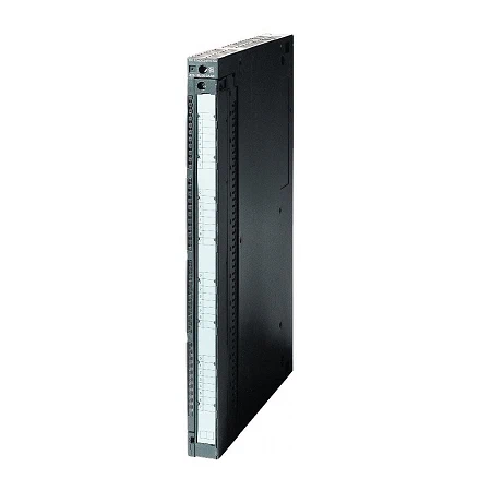
Digital output modules can be used to output digital signals from the control to the process. They are suitable, for example, for connecting solenoid valves, contactors, low-power motors, lamps and motor starters.
| Article number | 6ES7422-1FH00-0AA0 | 6ES7422-1HH00-0AA0 | 6ES7422-1BH11-0AA0 | 6ES7422-1BL00-0AA0 | 6ES7422-7BL00-0AB0 | |
| SM422, 16DO, AC120/230V, 2A | SM422, 16DO, AC5-230V, 5A RELAY | SM422, 16DO, DC24V, 2A, | SIMATIC S7-400, SM 422 | SIMATIC S7-400, DIG.OUTPUT MOD. | ||
| Supply voltage | ||||||
| Load voltage L+ | ||||||
| ● Rated value (DC) | 60 V | 24 V | 24 V | 24 V | ||
| ● permissible range, lower limit (DC) | 1 V | 20.4 V | 20.4 V | 20.4 V | ||
| ● permissible range, upper limit (DC) | 60 V | 28.8 V | 28.8 V | 28.8 V | ||
| Load voltage L1 | ||||||
| ● Rated value (AC) | 230 V; 120/230 V AC | 230 V | ||||
| ● permissible range, lower limit (AC) | 79 V | 2 V | ||||
| ● permissible range, upper limit (AC) | 264 V | 264 V | ||||
| ● permissible frequency range, lower limit | 47 Hz | |||||
| ● permissible frequency range, upper limit | 63 Hz | |||||
| Input current | ||||||
| from load voltage L+ (without load), max. | 1.5 mA | 30 mA | 30 mA | 120 mA | ||
| from backplane bus 5 V DC, max. | 400 mA | 1 A | 160 mA | 200 mA | 200 mA | |
| Power loss | ||||||
| Power loss, typ. | 16 W | 4.5 W | 5 W | 4 W | 8 W | |
| Digital outputs | ||||||
| Number of digital outputs | 16 | 16; Relays | 16 | 32 | 32 | |
| Short-circuit protection | Yes; Fuse 8 A, 250 V; per group | No | Yes; Clocked electronically | Yes; Clocked electronically | Yes; Clocked electronically | |
| ● Response threshold, typ. | 2.8 to 6 A | 0.7 to 1.5 A | 0.75 to 1.5 A | |||
| ● required current for fuse shutdown, min. | 100 A | |||||
| ● Response time, max. | 100 ms | |||||
| Limitation of inductive shutdown voltage to | -30 V | -27 V | L+ (-45 V) | |||
| Controlling a digital input | Yes; possible | Yes; possible | Yes; possible | Yes; possible | Yes; possible | |
| Size of motor starters according to NEMA, max. | Size 5 according to NEMA | Size 5 according to NEMA | ||||
| Spare fuses | Fuse 8 A, 250 V, quick response | |||||
| Zero-crossing switch | No | |||||
| Switching capacity of the outputs | ||||||
| ● on lamp load, max. | 50 W | 60 W | 10 W | 5 W | 5 W | |
| Load resistance range | ||||||
| ● lower limit | 24 Ω | 48 Ω | 48 Ω | |||
| ● upper limit | 4 kΩ | 4 kΩ | 4 kΩ | |||
| Output voltage | ||||||
| ● for signal “1”, min. | L1 (-18.1 V) | L+ (-0.5 V) | L+ (-0.3 V) | L+ (-0.8 V) | ||
| ● for signal “1” (at max. current), min. | L1 (-1.3 Vrms) | |||||
| ● for signal “1” (at min. current), min. | L1 (-18.1 Vrms) | |||||
| Output current | ||||||
| ● for signal “1” rated value | 2 A | 5 A | 2 A | 0.5 A | 0.5 A | |
| ● for signal “1” permissible range, min. | 10 mA | 5 mA | 5 mA | 5 mA | ||
| ● for signal “1” permissible range, max. | 2 A | 2.4 A | 0.6 A | 600 A | ||
| ● for signal “1” permissible surge current, max. | 50 A; per cycle | |||||
| ● for signal “0” residual current, max. | 2.6 mA | 0.5 mA | 0.3 mA | 0.5 mA | ||
| Output delay with resistive load | ||||||
| ● “0” to “1”, max. | 1 ms | 1 ms | 1 ms | |||
| ● “1” to “0”, max. | 1 AC cycle | 1 ms | 1 ms | |||
| Parallel switching of two outputs | ||||||
| ● for uprating | No; Not possible | No; Not possible | Yes; possible (only outputs of the same group) | Yes; possible (only outputs of the same group) | ||
| ● for redundant control of a load | Yes; Possible (only outputs with the same load voltage) | Yes; Possible (only outputs with the same load voltage) | Yes; possible (only outputs of the same group) | Yes; possible (only outputs of the same group) | Yes; possible (only outputs of the same group) | |
| Switching frequency | ||||||
| ● with resistive load, max. | 10 Hz | 10 Hz | 100 Hz | 100 Hz | 100 Hz | |
| ● with inductive load, max. | 0.5 Hz | 0.1 Hz | 0.5 Hz | 2 Hz | ||
| ● with inductive load (acc. to IEC 60947-5-1, DC13), max. | 0.2 Hz; 0.2 Hz at 1 A; 0.1 Hz at 2 A | 2 Hz; 2 Hz at 0.3 A; 0.5 Hz at 0.5 A | 2 Hz | |||
| ● with inductive load (acc. to IEC 60947-5-1, AC15), max. | 0.5 Hz | |||||
| ● With inductive load (to IEC 60947-5-1, DC13/AC15), max. | 1 Hz | |||||
| ● on lamp load, max. | 1 Hz | 1 Hz | 10 Hz | 10 Hz | 2 Hz | |
| ● mechanical, max. | 20 Hz | |||||
| Total current of the outputs (per group) | ||||||
| all mounting positions | ||||||
| — up to 40 °C, max. | 4 A; 6 A with fan assembly | 10 A; 10 A with fan subassembly | 3 A | 4 A | 4 A | |
| — up to 60 °C, max. | 2 A; 5 A with fan subassembly; per 4 adjacent outputs | 5 A; 10 A with fan subassembly | 2 A; 2 adjacent outputs each | 2 A; 8 adjacent outputs each | 2 A | |
| Relay outputs | ||||||
| ● Number of operating cycles, max. | 100 000; 100 000 (AC-15 / DC-13); 3 000 000 mechanical | |||||
| Switching capacity of contacts | ||||||
| — with inductive load, max. | 5 A; 5 A (30 V DC), 5 A (230 V AC) | |||||
| — with resistive load, max. | 5 A; 5 A (30 V DC), 5 A (230 V AC), 1.2 A (60 V DC), 0.2 A (125 V DC) | |||||
| — Thermal continuous current, max. | 5 A | |||||
| Cable length | ||||||
| ● shielded, max. | 1 000 m | 1 000 m | 1 000 m | 1 000 m | 1 000 m | |
| ● unshielded, max. | 600 m | 600 m | 600 m | 600 m | 600 m | |
| Interrupts/diagnostics/status information | ||||||
| Diagnostics function | Not parameterizable | No | No | No | Yes; Parameterizable | |
| Alarms | ||||||
| ● Diagnostic alarm | Yes; Parameterizable | |||||
| ● Hardware interrupt | Yes; Parameterizable | |||||
| Diagnoses | ||||||
| ● Diagnostic information readable | Yes | |||||
| ● Wire-break | Yes; <0.15 mA | |||||
| ● Short-circuit | Yes; > 1 A (typ.) | |||||
| Diagnostics indication LED | ||||||
| ● internal fault INTF (red) | Yes; Fuse blown | Yes | ||||
| ● external fault EXTF (red) | Yes; Missing load voltage | Yes | ||||
| ● Status indicator digital output (green) | Yes | |||||
| Potential separation | ||||||
| Potential separation digital outputs | ||||||
| ● between the channels | Yes | Yes | Yes | No | Yes | |
| ● between the channels, in groups of | 4 | 2 | 8 | 32 | 8 | |
| ● between the channels and backplane bus | Yes | Yes | Yes | Yes | Yes | |
| Isolation | ||||||
| Isolation tested with | 1 500 V AC | 1 500 V AC | 500 V DC | 500 V DC | 500 V DC | |
| Dimensions | ||||||
| Width | 25 mm | 25 mm | 25 mm | 25 mm | 25 mm | |
| Height | 290 mm | 290 mm | 290 mm | 290 mm | 290 mm | |
| Depth | 210 mm | 210 mm | 210 mm | 210 mm | 210 mm | |
| Weights | ||||||
| Weight, approx. | 800 g | 700 g | 600 g | 600 g | 600 g | |