USD 213.84 – USD 964.08Price range: USD 213.84 through USD 964.08
Digital input/output modules are suitable for connecting
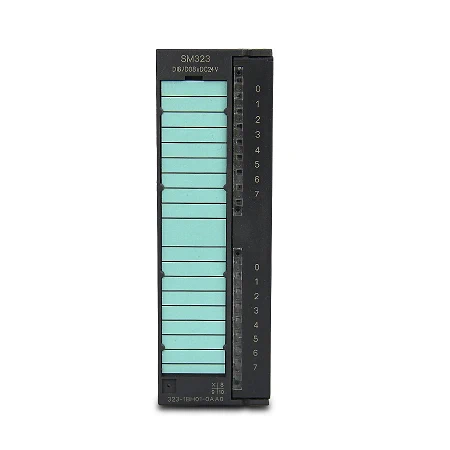
| Article number | 6ES7323-1BH01-0AA0 | 6ES7323-1BL00-0AA0 |
| SM323, 8DI/8DO, DC24V, 0,5A | SM323, 16DI/DO, DC24V, 0,5A | |
| Supply voltage | ||
| Load voltage L+ | ||
| ● Rated value (DC) | 24 V | 24 V |
| ● permissible range, lower limit (DC) | 20.4 V | 20.4 V |
| ● permissible range, upper limit (DC) | 28.8 V | 28.8 V |
| Input current | ||
| from load voltage L+ (without load), max. | 40 mA | 80 mA |
| from backplane bus 5 V DC, max. | 40 mA | 80 mA |
| Power loss | ||
| Power loss, typ. | 3.5 W | 6.5 W |
| Digital inputs | ||
| Number of digital inputs | 8 | 16 |
| Input characteristic curve in accordance with IEC 61131, type 1 | Yes | Yes |
| Number of simultaneously controllable inputs | ||
| horizontal installation | ||
| — up to 40 °C, max. | 16 | |
| — up to 60 °C, max. | 8 | 8 |
| vertical installation | ||
| — up to 40 °C, max. | 8 | 16 |
| Input voltage | ||
| ● Type of input voltage | DC | DC |
| ● Rated value (DC) | 24 V | 24 V |
| ● for signal “0” | -30 to +5 V | -30 to +5 V |
| ● for signal “1” | 13 to 30V | 13 to 30V |
| Input current | ||
| ● for signal “1”, typ. | 7 mA | 7 mA |
| Input delay (for rated value of input voltage) | ||
| for standard inputs | ||
| — at “0” to “1”, min. | 1.2 ms | 1.2 ms |
| — at “0” to “1”, max. | 4.8 ms | 4.8 ms |
| — at “1” to “0”, min. | 1.2 ms | 1.2 ms |
| — at “1” to “0”, max. | 4.8 ms | 4.8 ms |
| Cable length | ||
| ● shielded, max. | 1 000 m | 1 000 m |
| ● unshielded, max. | 600 m | 600 m |
| Digital outputs | ||
| Number of digital outputs | 8 | 16 |
| Short-circuit protection | Yes | Yes |
| ● Response threshold, typ. | 1 A | 1 A |
| Limitation of inductive shutdown voltage to | L+ (-53 V) | L+ (-48 V) |
| Controlling a digital input | Yes | Yes |
| Switching capacity of the outputs | ||
| ● on lamp load, max. | 5 W | 5 W |
| Load resistance range | ||
| ● lower limit | 48 Ω | 48 Ω |
| ● upper limit | 4 kΩ | 4 kΩ |
| Output voltage | ||
| ● for signal “1”, min. | L+ (-0.8 V) | L+ (-0.8 V) |
| Output current | ||
| ● for signal “1” rated value | 0.5 A | 0.5 A |
| ● for signal “1” permissible range, min. | 5 mA | 5 mA |
| ● for signal “1” permissible range, max. | 0.6 A | 0.6 A |
| ● for signal “1” minimum load current | 5 mA | 5 mA |
| ● for signal “0” residual current, max. | 0.5 mA | 0.5 mA |
| Output delay with resistive load | ||
| ● “0” to “1”, max. | 100 µs | 100 µs |
| ● “1” to “0”, max. | 500 µs | 500 µs |
| Parallel switching of two outputs | ||
| ● for uprating | No | No |
| ● for redundant control of a load | Yes; only outputs of the same group | Yes; only outputs of the same group |
| Switching frequency | ||
| ● with resistive load, max. | 100 Hz | 100 Hz |
| ● with inductive load, max. | 0.5 Hz | 0.5 Hz |
| ● with inductive load (acc. to IEC 60947-5-1, DC13), max. | 0.5 Hz | |
| ● on lamp load, max. | 10 Hz | 100 Hz |
| Total current of the outputs (per group) | ||
| horizontal installation | ||
| — up to 40 °C, max. | 4 A | 4 A |
| — up to 60 °C, max. | 4 A | 3 A |
| vertical installation | ||
| — up to 40 °C, max. | 4 A | 2 A |
| Cable length | ||
| ● shielded, max. | 1 000 m | 1 000 m |
| ● unshielded, max. | 600 m | 600 m |
| Encoder | ||
| Connectable encoders | ||
| ● 2-wire sensor | Yes | Yes |
| — permissible quiescent current (2-wire sensor), max. | 2 mA | 1.5 mA |
| Interrupts/diagnostics/status information | ||
| Alarms | No | No |
| Diagnostics function | No | No |
| Diagnostics indication LED | ||
| ● Status indicator digital input (green) | Yes | Yes |
| ● Status indicator digital output (green) | Yes | Yes |
| Potential separation | ||
| Potential separation digital inputs | ||
| ● between the channels | Yes | Yes |
| ● between the channels, in groups of | 8 | 16 |
| ● between the channels and backplane bus | Yes; Optocoupler | Yes; Optocoupler |
| Potential separation digital outputs | ||
| ● between the channels | Yes | Yes |
| ● between the channels, in groups of | 8 | 8 |
| ● between the channels and backplane bus | Yes; Optocoupler | Yes; Optocoupler |
| Isolation | ||
| Isolation tested with | 500 V DC | 500 V DC |
| connection method / header | ||
| required front connector | 20-pin | 40-pin |
| Dimensions | ||
| Width | 40 mm | 40 mm |
| Height | 125 mm | 125 mm |
| Depth | 120 mm | 120 mm |
| Weights | ||
| Weight, approx. | 220 g | 260 g |