USD 290.72 – USD 777.60Price range: USD 290.72 through USD 777.60
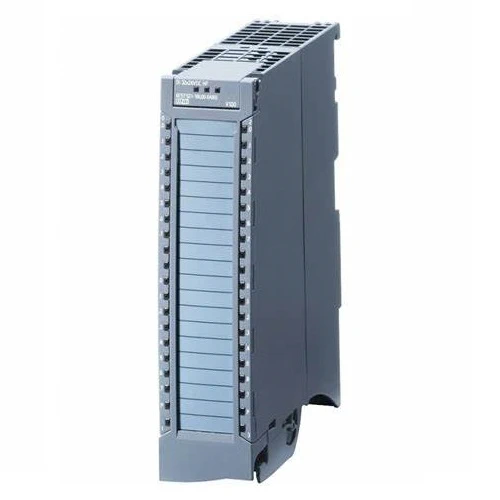
Digital input modules record 24 V DC or 230 V AC signals in the plant and forward them to the PLC. Switches and 2, 3 or 4-wire proximity switches can be connected.
High Feature modules feature configurable parameters and diagnostic functions and can thus be freely adapted to the respective process requirements.
Low cost input modules do not have settable parameters or diagnostic functions and are therefore very easy to integrate into the engineering. They are recommended for use in locations where only very few input channels are necessary or under conditions of use in which a high number of channels must be implemented in a very limited space.
Both module types can be used side by side in one station as required. Standardized features and shared system accessories guarantee easy handling.
The following digital input modules with a width of 35 mm are available:
The following digital input modules with a width of 25 mm are available:
| Article number | 6ES7521-1BH00-0AB0 | 6ES7521-1BL00-0AB0 | 6ES7521-1BH50-0AA0 | 6ES7521-1FH00-0AA0 | |
| S7-1500, DI 16x24VDC HF | S7-1500, DI 32x24VDC HF | S7-1500, DI 16x24VDC SRC BA | S7-1500, DI 16x230VAC BA | ||
| General information | |||||
| Product type designation | DI 16x24VDC HF | DI 32x24VDC HF | DI 16x24VDC SRC BA | DI 16x230VAC BA | |
| HW functional status | from FS04 | from FS04 | FS01 | FS01 | |
| Firmware version | V2.2.0 | V2.2.1 | V2.0.0 | V2.0.0 | |
| ● FW update possible | Yes | Yes | Yes | Yes | |
| Product function | |||||
| ● I&M data | Yes; I&M0 to I&M3 | Yes; I&M0 to I&M3 | Yes; I&M0 to I&M3 | Yes; I&M0 to I&M3 | |
| ● Isochronous mode | Yes | Yes | No | No | |
| ● Prioritized startup | Yes | Yes | Yes | Yes | |
| Engineering with | |||||
| ● STEP 7 TIA Portal configurable/integrated from version | V13 SP1 / – | V13 SP1 / – | V12 / V12 | V12 / V12 | |
| ● STEP 7 configurable/integrated from version | V5.5 SP3 / – | V5.5 SP3 / – | V5.5 SP3 / – | V5.5 SP3 / – | |
| ● PROFIBUS from GSD version/GSD revision | V1.0 / V5.1 | V1.0 / V5.1 | V1.0 / V5.1 | V1.0 / V5.1 | |
| ● PROFINET from GSD version/GSD revision | V2.3 / – | V2.3 / – | V2.3 / – | V2.3 / – | |
| Operating mode | |||||
| ● DI | Yes | Yes | Yes | Yes | |
| ● Counter | Yes | Yes | No | No | |
| ● Oversampling | No | No | |||
| ● MSI | Yes | Yes | Yes | Yes | |
| Supply voltage | |||||
| Rated value (DC) | 24 V | 24 V | |||
| permissible range, lower limit (DC) | 19.2 V | 19.2 V | 19.2 V | ||
| permissible range, upper limit (DC) | 28.8 V | 28.8 V | 28.8 V | ||
| Reverse polarity protection | Yes | Yes | |||
| external protection for power supply lines (recommendation) | |||||
| Input current | |||||
| Current consumption, max. | 20 mA; with 24 V DC supply | 40 mA; 20 mA per group with 24 V DC supply | |||
| Encoder supply | |||||
| Number of outputs | |||||
| Short-circuit protection | |||||
| 24 V encoder supply | |||||
| ● 24 V | |||||
| ● Short-circuit protection | |||||
| ● Output current, max. | |||||
| ● Output current per module, max. | |||||
| Power | |||||
| Power available from the backplane bus | 1.1 W | 1.1 W | 0.9 W | 1 W | |
| Power loss | |||||
| Power loss, typ. | 2.6 W | 4.2 W | 2.8 W | 4.9 W | |
| Digital inputs | |||||
| Number of digital inputs | 16 | 32 | 16 | 16 | |
| Digital inputs, parameterizable | Yes | Yes | No | No | |
| Source/sink input | P-reading | P-reading | Sourcing | P-reading | |
| Input characteristic curve in accordance with IEC 61131, type 1 | Yes | ||||
| Input characteristic curve in accordance with IEC 61131, type 2 | |||||
| Input characteristic curve in accordance with IEC 61131, type 3 | Yes | Yes | Yes | ||
| Pulse extension | |||||
| Edge evaluation | |||||
| Signal change flutter | |||||
| Flutter observation window | |||||
| Number of simultaneously controllable inputs | |||||
| ● Number of simultaneously controllable inputs | |||||
| Digital input functions, parameterizable | |||||
| ● Gate start/stop | Yes | Yes | |||
| ● Freely usable digital input | Yes | Yes | |||
| ● Counter | |||||
| — Number, max. | 2 | 2 | |||
| — Counting frequency, max. | 6 kHz | 6 kHz; FS04 and FW V2.2.1 or higher | |||
| — Counting width | 32 bit | 32 bit | |||
| — Counting direction up/down | Up | Up | |||
| ● Digital input with oversampling | |||||
| — Number, max. | |||||
| — Values per cycle, max. | |||||
| — Resolution, min. | |||||
| Input voltage | |||||
| ● Rated value (DC) | 24 V | 24 V | 24 V | ||
| ● Rated value (AC) | 230 V; 120/230 V AC, 50/60 Hz | ||||
| ● for signal “0” | -30 to +5 V | -30 to +5 V | -5 to +30V | 0V AC to 40V AC | |
| ● for signal “1” | +11 to +30V | +11 to +30V | -11 to -30V | 79V AC to 264V AC | |
| Input current | |||||
| ● for signal “1”, typ. | 2.5 mA | 2.5 mA | 4.5 mA | 11 mA; At 230 V AC and 5.5 mA at 120 V AC | |
| Input delay (for rated value of input voltage) | |||||
| for standard inputs | |||||
| — parameterizable | Yes; 0.05 / 0.1 / 0.4 / 1.6 / 3.2 / 12.8 / 20 ms | Yes; 0.05 / 0.1 / 0.4 / 1.6 / 3.2 / 12.8 / 20 ms | No | No | |
| — at “0” to “1”, min. | 0.05 ms | 0.05 ms | 3 ms | ||
| — at “0” to “1”, max. | 20 ms | 20 ms | 4 ms | 25 ms | |
| — at “1” to “0”, min. | 0.05 ms | 0.05 ms | 3 ms | ||
| — at “1” to “0”, max. | 20 ms | 20 ms | 4 ms | 25 ms | |
| for interrupt inputs | |||||
| — parameterizable | Yes | Yes | No | No | |
| for technological functions | |||||
| — parameterizable | Yes | Yes | No | No | |
| Cable length | |||||
| ● shielded, max. | 1 000 m | 1 000 m | 1 000 m | 1 000 m | |
| ● unshielded, max. | 600 m | 600 m | 600 m | 600 m | |
| Encoder | |||||
| Connectable encoders | |||||
| ● 2-wire sensor | Yes | Yes | Yes | Yes | |
| — permissible quiescent current (2-wire sensor), max. | 1.5 mA | 1.5 mA | 1.5 mA | 2 mA | |
| Isochronous mode | |||||
| Filtering and processing time (TCI), min. | 80 µs; At 50 μs filter time | 80 µs; At 50 μs filter time | |||
| Bus cycle time (TDP), min. | 250 µs | 250 µs | |||
| Interrupts/diagnostics/status information | |||||
| Diagnostics function | Yes | Yes | No | No | |
| Alarms | |||||
| ● Diagnostic alarm | Yes | Yes | No | No | |
| ● Hardware interrupt | Yes | Yes | No | No | |
| Diagnoses | |||||
| ● Monitoring the supply voltage | Yes | Yes | No | No | |
| ● Monitoring of encoder power supply | |||||
| ● Wire-break | Yes; to I < 350 µA | Yes; to I < 350 µA | No | No | |
| ● Short-circuit | No | No | No | No | |
| ● Group error | |||||
| Diagnostics indication LED | |||||
| ● RUN LED | Yes; green LED | Yes; green LED | Yes; green LED | Yes; green LED | |
| ● ERROR LED | Yes; red LED | Yes; red LED | Yes; red LED | Yes; red LED | |
| ● MAINT LED | |||||
| ● Monitoring of the supply voltage (PWR-LED) | Yes; green LED | Yes; green LED | No | No | |
| ● Channel status display | Yes; green LED | Yes; green LED | Yes; green LED | Yes; green LED | |
| ● for channel diagnostics | Yes; red LED | Yes; red LED | No | No | |
| ● for module diagnostics | Yes; red LED | Yes; red LED | No | Yes; red LED | |
| Potential separation | |||||
| Potential separation channels | |||||
| ● between the channels | No | Yes | No | No | |
| ● between the channels, in groups of | 16 | 16 | 16 | 4 | |
| ● between the channels and backplane bus | Yes | Yes | Yes | Yes | |
| ● Between the channels and load voltage L+ | |||||
| ● between the channels and the power supply of the electronics | No | No | |||
| Permissible potential difference | |||||
| between different circuits | 250 V AC between the channels and the backplane bus; 500 V AC between the channels | ||||
| Isolation | |||||
| Isolation tested with | 707 V DC (type test) | 707 V DC (type test) | 707 V DC (type test) | 3 100 V DC | |
| Standards, approvals, certificates | |||||
| Suitable for safety functions | No | No | No | No | |
| Ambient conditions | |||||
| Ambient temperature during operation | |||||
| ● horizontal installation, min. | -30 °C; From FS05 | -30 °C; From FS05 | 0 °C | 0 °C | |
| ● horizontal installation, max. | 60 °C | 60 °C | 60 °C | 60 °C | |
| ● vertical installation, min. | -30 °C; From FS05 | -30 °C; From FS05 | 0 °C | 0 °C | |
| ● vertical installation, max. | 40 °C | 40 °C | 40 °C | 40 °C | |
| Altitude during operation relating to sea level | |||||
| ● Installation altitude above sea level, max. | 5 000 m; Restrictions for installation altitudes > 2 000 m, see manual | 5 000 m; Restrictions for installation altitudes > 2 000 m, see manual | 5 000 m; Restrictions for installation altitudes > 2 000 m, see manual | ||
| Dimensions | |||||
| Width | 35 mm | 35 mm | 35 mm | 35 mm | |
| Height | 147 mm | 147 mm | 147 mm | 147 mm | |
| Depth | 129 mm | 129 mm | 129 mm | 129 mm | |
| Weights | |||||
| Weight, approx. | 240 g | 260 g | 230 g | 300 g | |
| Other | |||||
| Note: | |||||
| Article number | 6ES7521-7EH00-0AB0 | |
| S7-1500, DI 16 x 24…125V UC HF | ||
| General information | ||
| Product type designation | DI 16×24 … 125 V UC HF | |
| HW functional status | FS01 | |
| Firmware version | V1.0.0 | |
| ● FW update possible | Yes | |
| Product function | ||
| ● I&M data | Yes; I&M0 to I&M3 | |
| ● Isochronous mode | No | |
| ● Prioritized startup | Yes | |
| Engineering with | ||
| ● STEP 7 TIA Portal configurable/integrated from version | V13 SP1 / – | |
| ● STEP 7 configurable/integrated from version | V5.5 SP3 / – | |
| ● PROFIBUS from GSD version/GSD revision | V1.0 / V5.1 | |
| ● PROFINET from GSD version/GSD revision | V2.3 / – | |
| Operating mode | ||
| ● DI | Yes | |
| ● Counter | No | |
| ● Oversampling | No | |
| ● MSI | Yes | |
| Supply voltage | ||
| Rated value (DC) | ||
| permissible range, lower limit (DC) | ||
| permissible range, upper limit (DC) | ||
| Reverse polarity protection | ||
| Input current | ||
| Current consumption, max. | ||
| Encoder supply | ||
| Number of outputs | ||
| Short-circuit protection | ||
| NAMUR encoder supply | ||
| ● 8.2 V | ||
| ● Short-circuit protection | ||
| ● Output current, max. | ||
| ● Output current per module, max. | ||
| Power | ||
| Power available from the backplane bus | 1.2 W | |
| Power loss | ||
| Power loss, typ. | 2.2 W; At 24 V DC; 6.0 W at 125 V AC | |
| Digital inputs | ||
| Number of digital inputs | 16 | |
| Digital inputs, parameterizable | Yes | |
| Source/sink input | Yes | |
| Input characteristic curve in accordance with IEC 61131, type 3 | Yes; At 24 V DC | |
| Pulse extension | ||
| Edge evaluation | ||
| Signal change flutter | ||
| Flutter observation window | ||
| Digital input functions, parameterizable | ||
| ● Gate start/stop | ||
| ● Freely usable digital input | ||
| ● Counter | ||
| — Number, max. | ||
| — Counting frequency, max. | ||
| — Counting width | ||
| — Counting direction up/down | ||
| Input voltage | ||
| ● Rated value (DC) | 24 V; 48 V, 125 V | |
| ● Rated value (AC) | 24 V; 48 V, 125 V (50 – 60 Hz) | |
| ● for signal “0” | -5 … +5 V | |
| ● for signal “1” | +11 … +146 V | |
| Input current | ||
| ● for signal “1”, typ. | 3 mA; At 24 V DC | |
| for 10 k switched contact | ||
| — for signal “0” | ||
| — for signal “1” | ||
| for unswitched contact | ||
| — for signal “0”, max. (permissible quiescent current) | ||
| — for signal “1” | ||
| for NAMUR encoders | ||
| — for signal “0”, min. | ||
| — for signal “0”, max. | ||
| — for signal “1”, min. | ||
| — for signal “1”, max. | ||
| Input delay (for rated value of input voltage) | ||
| for standard inputs | ||
| — parameterizable | Yes; 0.05 / 0.1 / 0.4 / 1.6 / 3.2 / 12.8 / 20 ms parameterizable with DC, 20 ms fixed with AC | |
| — at “0” to “1”, min. | 0.05 ms | |
| — at “0” to “1”, max. | 20 ms | |
| — at “1” to “0”, min. | 0.05 ms | |
| — at “1” to “0”, max. | 20 ms | |
| for interrupt inputs | ||
| — parameterizable | Yes | |
| for technological functions | ||
| — parameterizable | No | |
| for NAMUR inputs | ||
| — at “0” to “1”, max. | ||
| — at “1” to “0”, max. | ||
| Cable length | ||
| ● shielded, max. | 1 000 m | |
| ● unshielded, max. | 600 m | |
| Encoder | ||
| Connectable encoders | ||
| ● NAMUR encoder/changeover contact according to EN 60947 | ||
| ● Single contact / changeover contact unconnected | ||
| ● Single contact / changeover contact connected with 10 kΩ | ||
| ● 2-wire sensor | Yes | |
| — permissible quiescent current (2-wire sensor), max. | 1.5 mA | |
| Isochronous mode | ||
| Filtering and processing time (TCI), min. | ||
| Bus cycle time (TDP), min. | ||
| Interrupts/diagnostics/status information | ||
| Diagnostics function | Yes | |
| Alarms | ||
| ● Diagnostic alarm | Yes | |
| ● Hardware interrupt | Yes | |
| Diagnoses | ||
| ● Monitoring the supply voltage | No | |
| ● Monitoring of encoder power supply | ||
| ● Wire-break | Yes; To I < 550 µA | |
| ● Short-circuit | No | |
| Diagnostics indication LED | ||
| ● RUN LED | Yes; green LED | |
| ● ERROR LED | Yes; red LED | |
| ● Monitoring of the supply voltage (PWR-LED) | No | |
| ● Channel status display | Yes; green LED | |
| ● for channel diagnostics | Yes; red LED | |
| ● for module diagnostics | Yes; red LED | |
| Potential separation | ||
| Potential separation channels | ||
| ● between the channels | Yes | |
| ● between the channels, in groups of | 1 | |
| ● between the channels and backplane bus | Yes | |
| ● Between the channels and load voltage L+ | ||
| ● between the channels and the power supply of the electronics | ||
| Permissible potential difference | ||
| between different circuits | 146 V DC/132 V AC | |
| Isolation | ||
| Isolation tested with | 2 000 V DC | |
| Standards, approvals, certificates | ||
| Suitable for safety functions | No | |
| Ambient conditions | ||
| Ambient temperature during operation | ||
| ● horizontal installation, min. | 0 °C | |
| ● horizontal installation, max. | 60 °C | |
| ● vertical installation, min. | 0 °C | |
| ● vertical installation, max. | 40 °C | |
| Altitude during operation relating to sea level | ||
| ● Installation altitude above sea level, max. | ||
| Dimensions | ||
| Width | 35 mm | |
| Height | 147 mm | |
| Depth | 129 mm | |
| Weights | ||
| Weight, approx. | 240 g | |
| Article number | 6ES7521-1BH10-0AA0 | 6ES7521-1BL10-0AA0 | |
| S7-1500, DI 16x24VDC BA | S7-1500, DI 32x24VDC BA | ||
| General information | |||
| Product type designation | DI 16 x 24 V DC BA | DI 32x24VDC BA | |
| HW functional status | From FS01 | From FS01 | |
| Firmware version | V1.0.0 | V1.0.0 | |
| ● FW update possible | Yes | Yes | |
| Product function | |||
| ● I&M data | Yes; I&M0 to I&M3 | Yes; I&M0 to I&M3 | |
| ● Isochronous mode | No | No | |
| ● Prioritized startup | Yes | Yes | |
| Engineering with | |||
| ● STEP 7 TIA Portal configurable/integrated from version | V13 / V13 | V13 / V13 | |
| ● STEP 7 configurable/integrated from version | V5.5 SP3 / – | V5.5 SP3 / – | |
| ● PROFIBUS from GSD version/GSD revision | V1.0 / V5.1 | V1.0 / V5.1 | |
| ● PROFINET from GSD version/GSD revision | V2.3 / – | V2.3 / – | |
| Operating mode | |||
| ● DI | Yes | Yes | |
| ● Counter | No | No | |
| ● MSI | Yes | Yes | |
| Supply voltage | |||
| Rated value (DC) | 24 V | 24 V | |
| permissible range, lower limit (DC) | 19.2 V | 19.2 V | |
| permissible range, upper limit (DC) | 28.8 V | 28.8 V | |
| Power | |||
| Power available from the backplane bus | 1.05 W | 1.05 W | |
| Power loss | |||
| Power loss, typ. | 1.8 W | 3 W | |
| Digital inputs | |||
| Number of digital inputs | 16 | 32 | |
| Digital inputs, parameterizable | No | No | |
| Source/sink input | P-reading | P-reading | |
| Input characteristic curve in accordance with IEC 61131, type 3 | Yes | Yes | |
| Input voltage | |||
| ● Rated value (DC) | 24 V | 24 V | |
| ● for signal “0” | -30 to +5 V | -30 to +5 V | |
| ● for signal “1” | +11 to +30V | +11 to +30V | |
| Input current | |||
| ● for signal “1”, typ. | 2.7 mA | 2.7 mA | |
| Input delay (for rated value of input voltage) | |||
| for standard inputs | |||
| — parameterizable | No | No | |
| — at “0” to “1”, min. | 3 ms | 3 ms | |
| — at “0” to “1”, max. | 4 ms | 4 ms | |
| — at “1” to “0”, min. | 3 ms | 3 ms | |
| — at “1” to “0”, max. | 4 ms | 4 ms | |
| for interrupt inputs | |||
| — parameterizable | No | No | |
| for technological functions | |||
| — parameterizable | No | No | |
| Cable length | |||
| ● shielded, max. | 1 000 m | 1 000 m | |
| ● unshielded, max. | 600 m | 600 m | |
| Encoder | |||
| Connectable encoders | |||
| ● 2-wire sensor | Yes | Yes | |
| — permissible quiescent current (2-wire sensor), max. | 1.5 mA | 1.5 mA | |
| Interrupts/diagnostics/status information | |||
| Diagnostics function | No | No | |
| Alarms | |||
| ● Diagnostic alarm | No | No | |
| ● Hardware interrupt | No | No | |
| Diagnoses | |||
| ● Monitoring the supply voltage | No | No | |
| ● Wire-break | No | No | |
| ● Short-circuit | No | No | |
| Diagnostics indication LED | |||
| ● RUN LED | Yes; green LED | Yes; green LED | |
| ● ERROR LED | Yes; red LED | Yes; red LED | |
| ● Monitoring of the supply voltage (PWR-LED) | No | No | |
| ● Channel status display | Yes; green LED | Yes; green LED | |
| ● for channel diagnostics | No | No | |
| ● for module diagnostics | No | No | |
| Potential separation | |||
| Potential separation channels | |||
| ● between the channels | No | No | |
| ● between the channels, in groups of | 16 | 16 | |
| ● between the channels and backplane bus | Yes | Yes | |
| ● between the channels and the power supply of the electronics | No | ||
| Isolation | |||
| Isolation tested with | 707 V DC (type test) | 707 V DC (type test) | |
| Standards, approvals, certificates | |||
| Suitable for safety functions | No | No | |
| Ambient conditions | |||
| Ambient temperature during operation | |||
| ● horizontal installation, min. | -30 °C; from FS04 | -30 °C; from FS04 | |
| ● horizontal installation, max. | 60 °C | 60 °C | |
| ● vertical installation, min. | -30 °C; from FS04 | -30 °C; from FS04 | |
| ● vertical installation, max. | 40 °C | 40 °C | |
| Altitude during operation relating to sea level | |||
| ● Installation altitude above sea level, max. | 5 000 m; Restrictions for installation altitudes > 2 000 m, see manual | 5 000 m; Restrictions for installation altitudes > 2 000 m, see manual | |
| Dimensions | |||
| Width | 25 mm | 25 mm | |
| Height | 147 mm | 147 mm | |
| Depth | 129 mm | 129 mm | |
| Weights | |||
| Weight, approx. | 230 g | 260 g | |
| Other | |||
| Note: | Supplied incl. 40-pole push-in front connectors | Supplied incl. 40-pole push-in front connectors | |