USD 124.28 – USD 188.22Price range: USD 124.28 through USD 188.22
Scalable and cost-optimized configuration of a ET 200SP station is achieved by a comprehensive portfolio of digital and analog IO modules.
SIMATIC ET 200SP is about 50% narrower than other distributed peripheries. With its height of 115 millimeters, the system can accommodate 16 channels with single-wire connection (without AUX-plugs). For a 3-wire connection with AUX-plugs the height for 8 channels is 140 millimeters. The depth is 75 millimeters. In order to keep its small size, the power module for load group formation is integrated into the system of SIMATIC ET 200SP.
The peripheral modules are labelled with different colored squares to identify easily the type of module.
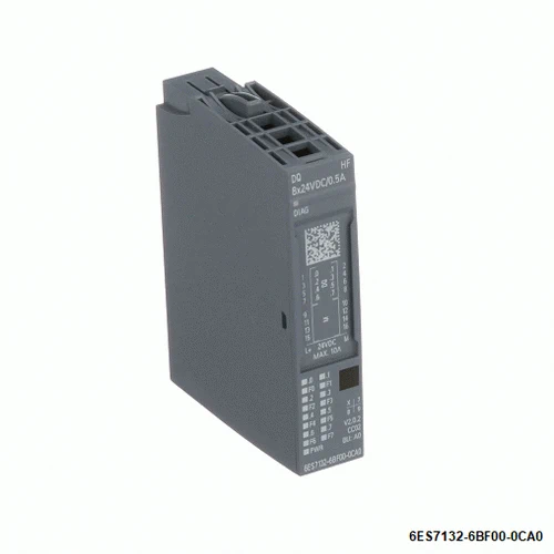
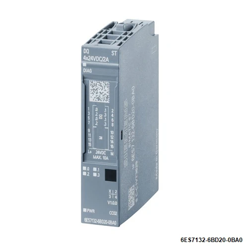
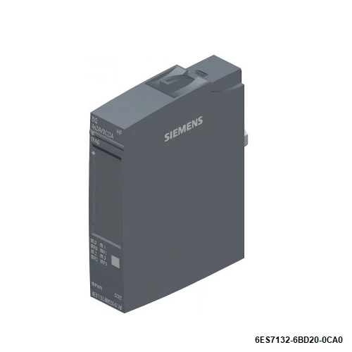
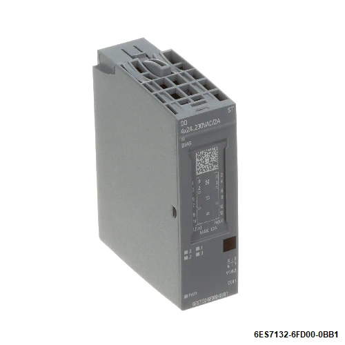
| Article number | 6ES7132-6BF00-0CA0 | 6ES7132-6BD20-0BA0 | 6ES7132-6BD20-0CA0 | 6ES7132-6BD20-0DA0 | 6ES7132-6FD00-0BB1 |
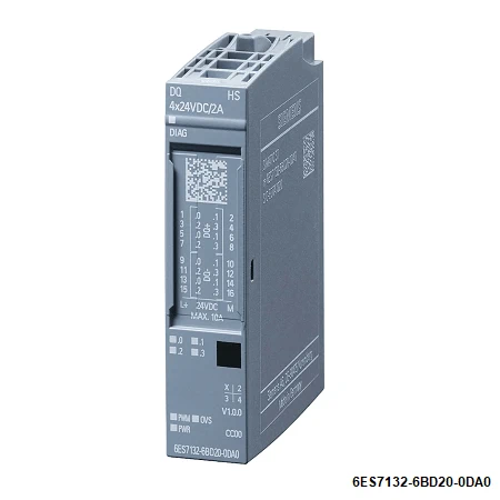
| ET 200SP, DQ 8x24VDC/0,5A HF, PU 1 | ET 200SP, DQ 4x24VDC/2A ST | ET 200SP, DQ 4x24VDC/2A HF | ET 200SP, DQ 4x24VDC/2A High Speed, PU 1 | ET 200SP, DQ 4×24..230VAC/2A ST | |
| General information | |||||
| Product type designation | DQ 8×24 V DC/0.5 A HF | DQ 4×24 V DC/2 A ST | DQ 4x DC 24 V/2 A HF | DQ 4×24 V DC/2 A HS | DQ 4×24 … 230 V AC/2 A ST |
| HW functional status | From FS07 | From FS08 | From FS06 | From FS05 | From FS05 |
| Firmware version | V1.1 | V1.0 | |||
| ● FW update possible | Yes | Yes | Yes | Yes | Yes |
| usable BaseUnits | BU type A0 | BU type A0 | BU type A0 | BU type A0 | BU type B1 |
| Color code for module-specific color identification plate | CC02 | CC02 | CC02 | CC00 | CC41 |
| Product function | |||||
| ● I&M data | Yes; I&M0 to I&M3 | Yes; I&M0 to I&M3 | Yes; I&M0 to I&M3 | Yes; I&M0 to I&M3 | Yes; I&M0 to I&M3 |
| ● Isochronous mode | Yes | No | Yes | Yes; Operating modes DQ and OVS only | No |
| Engineering with | |||||
| ● STEP 7 TIA Portal configurable/integrated from version | V13 SP1 / – | V11 SP2 / V13 | V13 SP1 / – | STEP 7 V15.1 or higher | V13 / V13 |
| ● STEP 7 configurable/integrated from version | V5.5 / – | V5.5 SP3 / – | V5.5 / – | via GSD as of V5.6 HF4 | V5.5 SP3 / – |
| ● PCS 7 configurable/integrated from version | V8.1 SP1 | V8.1 SP1 | |||
| ● PROFIBUS from GSD version/GSD revision | One GSD file each, Revision 3 and 5 and higher | GSD Revision 5 | GSD Revision 5 | One GSD file each, Revision 3 and 5 and higher | GSD Revision 5 |
| ● PROFINET from GSD version/GSD revision | GSDML V2.3 | GSDML V2.3 | GSDML V2.3 | GSDML V2.33 | GSDML V2.3 |
| Operating mode | |||||
| ● DQ | Yes | Yes | Yes | Yes | Yes |
| ● DQ with energy-saving function | No | No | No | Yes; Valve control | No |
| ● PWM | No | No | No | Yes | No |
| ● Cam control (switching at comparison values) | Yes; Via MtM (module-to-module communication) | ||||
| ● Oversampling | No | No | No | Yes | No |
| ● MSO | Yes | No | Yes | No | No |
| Supply voltage | |||||
| Rated value (DC) | 24 V | 24 V | 24 V | 24 V | |
| permissible range, lower limit (DC) | 19.2 V | 19.2 V | 19.2 V | 19.2 V | |
| permissible range, upper limit (DC) | 28.8 V | 28.8 V | 28.8 V | 28.8 V | |
| Rated value (AC) | 230 V | ||||
| permissible range, lower limit (AC) | 20.4 V | ||||
| permissible range, upper limit (AC) | 264 V | ||||
| Reverse polarity protection | Yes | Yes | Yes | Yes | |
| Input current | |||||
| Current consumption (rated value) | 11.5 mA | ||||
| Current consumption, max. | 60 mA; without load | 50 mA; without load | |||
| output voltage / header | |||||
| Rated value (DC) | 24 V | 24 V | 24 V | 24 V | |
| Rated value (AC) | 230 V; 24V AC to 230V AC | ||||
| Power loss | |||||
| Power loss, typ. | 1 W | 1 W | 1 W | 2.5 W; at 24 V, 25 °C, DQ mode, 2 A per channel | 9 W; Active power, load voltage 230 V, all outputs loaded with 2 A, 50 Hz |
| Address area | |||||
| Address space per module | |||||
| ● Address space per module, max. | 8 byte; 2 channels per submodule + QI information | 1 byte; + 1 byte for QI information | 4 byte; 2 channels per submodule + QI information | 1 byte; + 1 byte for QI information | |
| ● Inputs | 1 byte; Max. 14 bytes in the cam control operating mode | 1 byte; With QI | |||
| ● Outputs | 1 byte; Max. 16 bytes in the oversampling operating mode | 1 byte | |||
| Hardware configuration | |||||
| Automatic encoding | Yes | Yes | Yes | ||
| ● Mechanical coding element | Yes | Yes | Yes | Yes | |
| ● Type of mechanical coding element | Type A | Type A | Type A | Type A | type C |
| Selection of BaseUnit for connection variants | |||||
| ● 1-wire connection | BU type A0 | BU type A0 | BU type A0 | BU type A0 | |
| ● 2-wire connection | BU type A0 | BU type A0 | BU type A0 | BU type A0 | |
| ● 3-wire connection | BU type A0 with AUX terminals or potential distributor module | BU type A0 with AUX terminals or potential distributor module | BU type A0 with AUX terminals or potential distributor module | BU type A0 with AUX terminals or potential distributor module | |
| ● 4-wire connection | BU type A0 + Potential distributor module | BU type A0 + Potential distributor module | BU type A0 + Potential distributor module | BU type A0 + Potential distributor module | |
| Digital outputs | |||||
| Type of digital output | Source output (PNP, current-sourcing) | Source output (PNP, current-sourcing) | Source output (PNP, current-sourcing) | Source output (PNP, current-sourcing) | Triac with zero point detection |
| Number of digital outputs | 8 | 4 | 4 | 4 | 4 |
| Current-sinking | No | No | No | No | No |
| Current-sourcing | Yes | Yes | Yes | Yes; Push-pull output | Yes |
| Digital outputs, parameterizable | Yes | Yes | Yes | Yes | No |
| Short-circuit protection | Yes | Yes | Yes | Yes | No; When using BU type B1, a miniature, quick-response fuse with 10 A tripping current must be provided |
| ● Response threshold, typ. | 0.7 to 1.3 A | 2.8 to 5.2 A | 2.8 to 5.2 A | 6 A | |
| Limitation of inductive shutdown voltage to | Typ. L+ (-50 V) | Typ. L+ (-50 V) | L+ -(37 to 41V) | M (-1 V) | |
| Controlling a digital input | Yes | Yes | Yes; Minimum current consumption 7 mA | No | Yes |
| Size of motor starters according to NEMA, max. | 5 | ||||
| Digital output functions, parameterizable | |||||
| ● Switching tripped by comparison values | Yes | ||||
| — Number of cam tracks, max. | 4 | ||||
| — Number of cams per module, max. | 16 | ||||
| — Number of cams per track, max. | 16 | ||||
| — Supported axis types | Linear axes and rotary axes with modulo function | ||||
| — Hysteresis | Yes | ||||
| — Pulsed cam output | Yes | ||||
| — Range of values for comparison values, max. | -2,147,483,648 to 2,147,483,647 (user-specific within this range) | ||||
| ● Freely usable digital output | Yes | ||||
| ● PWM output | Yes | ||||
| — Number, max. | 4 | ||||
| — Cycle duration, parameterizable | Yes; 0 ms, 0.2 ms, 0.4 ms, 0.93 ms, 1.33 ms, 4.27 ms, 10.67 ms, 21.33 ms, 34.13 ms, 59.73 ms | ||||
| — Resolution of the duty cycle | 0.1 % | ||||
| ● Digital output with oversampling | Yes | ||||
| — Number, max. | 4 | ||||
| — Values per cycle, max. | 32 | ||||
| — Resolution, min. | 100 µs | ||||
| Switching capacity of the outputs | |||||
| ● with resistive load, max. | 0.5 A | 2 A | 2 A | 2 A | 2 A |
| ● on lamp load, max. | 5 W | 10 W | 10 W | 10 W | 100 W |
| Load resistance range | |||||
| ● lower limit | 48 Ω | 12 Ω | 12 Ω | 12 Ω | |
| ● upper limit | 12 kΩ | 3 400 Ω | 3 400 Ω | 3 400 Ω | |
| Output voltage | |||||
| ● for signal “1”, min. | 20.4 V | ||||
| Output current | |||||
| ● for signal “1” rated value | 0.5 A | 2 A | 2 A | 2 A | 2 A |
| ● for signal “1” permissible range, min. | 10 mA | ||||
| ● for signal “1” permissible range, max. | 2 A | ||||
| ● for signal “0” residual current, max. | 0.1 mA | 0.1 mA | 0.1 mA | 0.1 mA | 460 µA |
| Output delay with resistive load | |||||
| ● “0” to “1”, typ. | 50 µs | 50 µs | 50 µs | ||
| ● “0” to “1”, max. | 50 µs | 1 µs | 10 ms | ||
| ● “1” to “0”, typ. | 100 µs | 100 µs | 100 µs | ||
| ● “1” to “0”, max. | 100 µs | 1 µs | 10 ms | ||
| Parallel switching of two outputs | |||||
| ● for logic links | No | ||||
| ● for uprating | No | No | No | No | No |
| ● for redundant control of a load | Yes | Yes | Yes | ||
| Switching frequency | |||||
| ● with resistive load, max. | 100 Hz | 100 Hz | 100 Hz | 5 kHz | 10 Hz |
| ● with inductive load, max. | 2 Hz | 2 Hz | 2 Hz | 5 kHz | 0.5 Hz; Higher frequencies are possible, see Equipment Manual / Product Information |
| ● on lamp load, max. | 10 Hz | 10 Hz | 10 Hz | 5 kHz | 1 Hz |
| Total current of the outputs | |||||
| ● Current per channel, max. | 0.5 A | 2 A | 2 A | 2 A | 2 A |
| ● Current per module, max. | 4 A | 8 A | 8 A | 8 A | 8 A |
| Total current of the outputs (per module) | |||||
| horizontal installation | |||||
| — up to 30 °C, max. | 8 A; DQ mode | ||||
| — up to 40 °C, max. | 8 A | 8 A | 6.9 A; DQ mode | 8 A | |
| — up to 50 °C, max. | 6 A | 6 A | 4.7 A; DQ mode | 6 A | |
| — up to 60 °C, max. | 4 A | 4 A | 4 A | 2.5 A; DQ mode | 4 A |
| vertical installation | |||||
| — up to 30 °C, max. | 8 A | 8 A | 7.2 A; DQ mode | 8 A | |
| — up to 40 °C, max. | 6 A | 6 A | 5.6 A; DQ mode | 6 A | |
| — up to 50 °C, max. | 4 A | 4 A | 4 A | 4 A; DQ mode | 4 A |
| — up to 60 °C, max. | 4 A | ||||
| Cable length | |||||
| ● shielded, max. | 1 000 m | 1 000 m | 1 000 m | 50 m | 1 000 m |
| ● unshielded, max. | 600 m | 600 m | 600 m | 50 m | 600 m |
| Isochronous mode | |||||
| Execution and activation time (TCO), min. | 48 µs | 40 µs | |||
| Bus cycle time (TDP), min. | 500 µs | 500 µs | 125 µs | ||
| Jitter, max. | 8 µs | 1 µs | |||
| Interrupts/diagnostics/status information | |||||
| Diagnostics function | Yes | Yes | Yes | Yes | No |
| Substitute values connectable | Yes | Yes | Yes | Yes | Yes |
| Alarms | |||||
| ● Diagnostic alarm | Yes | Yes | Yes | Yes | No |
| Diagnoses | |||||
| ● Diagnostic information readable | Yes | ||||
| ● Monitoring the supply voltage | Yes | Yes | Yes | Yes | No |
| ● Wire-break | Yes; channel by channel | Yes; Module-wise | Yes; channel by channel | No | No |
| ● Short-circuit | Yes; channel by channel | Yes; Module-wise | Yes; channel by channel | Yes; Module-wise | No |
| ● Group error | Yes | Yes | Yes | Yes | Yes |
| Diagnostics indication LED | |||||
| ● Monitoring of the supply voltage (PWR-LED) | Yes; green PWR LED | Yes; green PWR LED | Yes; green PWR LED | Yes; green PWR LED | Yes; green PWR LED |
| ● Channel status display | Yes; green LED | Yes; green LED | Yes; green LED | Yes; green LED | Yes; green LED |
| ● for channel diagnostics | Yes; red LED | No | Yes; red LED | No | No |
| ● for module diagnostics | Yes; green/red DIAG LED | Yes; green/red DIAG LED | Yes; green/red DIAG LED | Yes; green/red DIAG LED | Yes; green/red DIAG LED |
| Potential separation | |||||
| Potential separation channels | |||||
| ● between the channels | No | No | No | No | No |
| ● between the channels and backplane bus | Yes | Yes | Yes | Yes | Yes |
| ● between the channels and the power supply of the electronics | No | No | No | ||
| Isolation | |||||
| Isolation tested with | 707 V DC (type test) | 707 V DC (type test) | 707 V DC (type test) | 707 V DC (type test) | 2 545 V DC/2 s (routine test) |
| Standards, approvals, certificates | |||||
| Suitable for safety functions | No | No | No | No | No |
| Suitable for safety-related tripping of standard modules | No; see FAQ Entry ID: 39198632 | Yes; see FAQ Entry ID: 39198632 | Yes; see FAQ Entry ID: 39198632 | No | |
| Highest safety class achievable in safety mode | |||||
| ● Performance level according to ISO 13849-1 | PL d | PL d | PL d | ||
| ● SIL acc. to IEC 61508 | SIL 2 | SIL 2 | SIL 2 | ||
| Ambient conditions | |||||
| Ambient temperature during operation | |||||
| ● horizontal installation, min. | -30 °C; < 0 °C as of FS07 | -30 °C; < 0 °C as of FS08 | -30 °C; < 0 °C as of FS06 | -30 °C | -30 °C |
| ● horizontal installation, max. | 60 °C | 60 °C | 60 °C | 60 °C | 60 °C |
| ● vertical installation, min. | -30 °C; < 0 °C as of FS07 | -30 °C; < 0 °C as of FS08 | -30 °C; < 0 °C as of FS06 | -30 °C | -30 °C |
| ● vertical installation, max. | 50 °C | 50 °C | 50 °C | 50 °C | 60 °C |
| Altitude during operation relating to sea level | |||||
| ● Installation altitude above sea level, max. | 5 000 m; Restrictions for installation altitudes > 2 000 m, see manual | 5 000 m; Restrictions for installation altitudes > 2 000 m, see manual | 5 000 m; Restrictions for installation altitudes > 2 000 m, see manual | 5 000 m; Restrictions for installation altitudes > 2 000 m, see manual | 2 000 m; On request: Installation altitudes greater than 2 000 m |
| Dimensions | |||||
| Width | 15 mm | 15 mm | 15 mm | 15 mm | 20 mm |
| Height | 73 mm | 73 mm | 73 mm | 73 mm | 73 mm |
| Depth | 58 mm | 58 mm | 58 mm | 58 mm | 58 mm |
| Weights | |||||
| Weight, approx. | 30 g | 30 g | 30 g | 31 g | 50 g |