USD 290.72
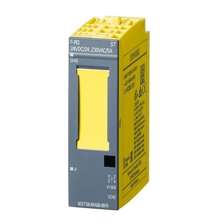
| Article number | 6ES7136-6RA00-0BF0 |
| ET 200SP, F-RQ 1x24VDC/24..230VAC/5A ST | |
| General information | |
| Product type designation | F-RQ 24 … 48VDC/24 … 230VAC/5A ST |
| usable BaseUnits | BU type F0 |
| Color code for module-specific color identification plate | CC42 |
| Product function | |
| ● I&M data | Yes; I&M0 to I&M3 |
| Engineering with | |
| ● STEP 7 TIA Portal configurable/integrated from version | V13 |
| ● STEP 7 configurable/integrated from version | V5.5 SP4 and higher |
| ● PROFINET from GSD version/GSD revision | V2.31 |
| Supply voltage | |
| Rated value (DC) | 24 V; Coil voltage |
| permissible range, lower limit (DC) | 20.4 V |
| permissible range, upper limit (DC) | 28.8 V |
| power supply according to NEC Class 2 required | No |
| Power | |
| Power available from the backplane bus | 100 mW |
| Power loss | |
| Power loss, typ. | 1 W |
| Address area | |
| Address space per module | |
| ● Inputs | 1 byte |
| Hardware configuration | |
| Automatic encoding | Yes |
| ● Mechanical coding element | Yes |
| ● Type of mechanical coding element | type C |
| Digital outputs | |
| Type of digital output | Relays |
| Number of digital outputs | 1 |
| Limitation of inductive shutdown voltage to | No |
| Controlling a digital input | Yes |
| Switching capacity of the outputs | |
| ● with resistive load, max. | 5 A |
| ● on lamp load, max. | 25 W |
| Switching frequency | |
| ● with resistive load, max. | 2 Hz |
| ● with inductive load, max. | 0.1 Hz; See data in manual |
| ● with inductive load (acc. to IEC 60947-5-1, DC13), max. | 0.1 Hz |
| ● with inductive load (acc. to IEC 60947-5-1, AC15), max. | 2 Hz |
| Total current of the outputs (per module) | |
| horizontal installation | |
| — up to 40 °C, max. | 5 A; note derating data in the manual |
| — up to 50 °C, max. | 4 A; note derating data in the manual |
| — up to 60 °C, max. | 3 A; note derating data in the manual |
| vertical installation | |
| — up to 50 °C, max. | 3 A; note derating data in the manual |
| Relay outputs | |
| ● Number of relay outputs | 1; 2 NO contacts |
| ● Rated supply voltage of relay coil L+ (DC) | 24 V |
| ● Current consumption of relays (coil current of all relays), max. | 70 mA |
| ● external protection for relay outputs | yes; 6 A, see data in manual |
| ● Relay approved acc. to UL 508 | Yes; Pilot Duty B300, R300 |
| Switching capacity of contacts | |
| — with inductive load, max. | see additional description in the manual |
| — with resistive load, max. | see additional description in the manual |
| — Thermal continuous current, max. | 5 A |
| — Switching current, min. | 1 mA |
| — Switching current after exceeding 300 mA, min. | 10 mA |
| — Switching current after exceeding 300 mA, max. | 5 A |
| — Rated switching voltage (DC) | 24 V |
| — Rated switching voltage (AC) | 230 V |
| Cable length | |
| ● shielded, max. | 500 m; for load contacts |
| ● unshielded, max. | 300 m; for load contacts |
| ● Control cable (input), max. | 10 m |
| Interrupts/diagnostics/status information | |
| Diagnostics function | Yes |
| Diagnostics indication LED | |
| ● RUN LED | Yes; green/red DIAG LED |
| ● Channel status display | Yes; green LED |
| Potential separation | |
| Potential separation channels | |
| ● between the channels | Yes; for SELV / PELV only |
| ● between the channels and backplane bus | Yes |
| ● between the channels and the power supply of the electronics | Yes |
| Permissible potential difference | |
| between channels and backplane bus/supply voltage | 250 V AC (reinforced insulation) |
| Isolation | |
| Isolation tested with | 2 545 V DC/2 s (routine test) |
| Overvoltage category | III |
| tested with | |
| ● between channels and backplane bus/supply voltage | DC 2 545 V 2 s (routine test), impulse voltage test DC 7 200 V / 5 positive and 5 negative pulses (type test) |
| ● between backplane bus and supply voltage | 707 V DC (type test) |
| Standards, approvals, certificates | |
| Suitable for safety functions | Yes |
| Highest safety class achievable in safety mode | |
| ● Performance level according to ISO 13849-1 | PLe |
| ● Category according to ISO 13849-1 | 4 |
| ● SIL acc. to IEC 61508 | SIL 3 |
| Probability of failure (for service life of 20 years and repair time of 100 hours) | |
| — Low demand mode: PFDavg in accordance with SIL2 | < 1.00E-04, function test 1x per year |
| — Low demand mode: PFDavg in accordance with SIL3 | < 1.00E-05, function test 1x per month |
| — High demand/continuous mode: PFH in accordance with SIL2 | < 1.00E-08 1/h, function test 1x per year |
| — High demand/continuous mode: PFH in accordance with SIL3 | < 6.00E-09 1/h, function test 1x per month |
| Ambient conditions | |
| Ambient temperature during operation | |
| ● horizontal installation, min. | 0 °C |
| ● horizontal installation, max. | 60 °C |
| ● vertical installation, min. | 0 °C |
| ● vertical installation, max. | 50 °C |
| Dimensions | |
| Width | 20 mm |
| Height | 73 mm |
| Depth | 58 mm |
| Weights | |
| Weight, approx. | 56 g |