$ 50.60 – $ 549.01Price range: $ 50.60 through $ 549.01
| Article number | 6ES7132-4BB01-0AB0 | 6ES7132-4BB01-0AA0 | 6ES7132-4BB31-0AB0 | 6ES7132-4BB31-0AA0 | 6ES7132-4BD00-0AB0 | 6ES7132-4BD02-0AA0 |
| ET200S, El-Mod., 2DO HF,DC24V, 0.5A, 5PC | ET200S, El-Mod., 2DO ST,DC24V, 0.5A, 5PC | ET200S, El-Mod., 2DO HF, DC 24V, 2A, 5PC | ET200S, El-Mod., 2DO ST, DC 24V, 2A, 5PC | ET200S, El-Mod., 4DO HF,DC24V, 0.5A,5pcs | ET200S, El-Mod., 4DO ST,DC24V, 0.5A,5pcs | |
| Supply voltage | ||||||
| Reverse voltage protection | Yes; when using the same load voltage as on the power module | Yes; when using the same load voltage as on the power module | Yes; when using the same load voltage as on the power module | Yes; when using the same load voltage as on the power module | Yes; when using the same load voltage as on the power module | Yes; when using the same load voltage as on the power module |
| Load voltage L+ | ||||||
| ● Rated value (DC) | 24 V; From power module | 24 V; From power module | 24 V; From power module | 24 V; From power module | 24 V; From power module | 24 V; From power module |
| ● Reverse polarity protection | Yes; polarity reversal can lead to the digital outputs being connected through | Yes; polarity reversal can lead to the digital outputs being connected through | Yes; polarity reversal can lead to the digital outputs being connected through | Yes; polarity reversal can lead to the digital outputs being connected through | Yes; polarity reversal can lead to the digital outputs being connected through | Yes; polarity reversal can lead to the digital outputs being connected through |
| Input current | ||||||
| from load voltage L+ (without load), max. | 5 mA; Per channel | 5 mA; Per channel | 5 mA; Per channel | 5 mA; Per channel | 5 mA; Per channel | 10 mA; Per channel |
| from backplane bus 3.3 V DC, max. | 10 mA | 10 mA | 10 mA | 10 mA | 10 mA | 10 mA |
| Power loss | ||||||
| Power loss, typ. | 0.4 W | 0.4 W | 1.4 W | 1.4 W | 0.8 W | 0.8 W |
| Address area | ||||||
| Address space per module | ||||||
| ● Address space per module, max. | 1 byte | 1 byte | 1 byte | 1 byte | 1 byte | 1 byte |
| ● with packing | 2 bit | 2 bit | 2 bit | 2 bit | 4 bit | 4 bit |
| Digital outputs | ||||||
| Type of digital output | Source output (PNP, current-sourcing) | Source output (PNP, current-sourcing) | Source output (PNP, current-sourcing) | Source output (PNP, current-sourcing) | Transistor | Source output (PNP, current-sourcing) |
| Number of digital outputs | 2 | 2 | 2 | 2 | 4 | 4 |
| Short-circuit protection | Yes | Yes | Yes | Yes | Yes | Yes |
| ● Response threshold, typ. | 1.5 A | 0.7 to 1.8 A | 4 A | 2.8 to 7.2 A | 0.7 to 1.5 A | 1 to 1.5 A |
| Limitation of inductive shutdown voltage to | -55 to -60 V, typ. L+( ) | -55 to -60 V, typ. L+( ) | -55 to -60 V, typ. L+( ) | -55 to -60 V, typ. L+( ) | -55 to -60 V, L+( ) | L+ (-55 to -60 V) |
| Controlling a digital input | Yes | Yes | Yes | Yes | Yes | Yes |
| Switching capacity of the outputs | ||||||
| ● on lamp load, max. | 2.5 W | 5 W | 5 W | 10 W | 5 W | 5 W |
| Load resistance range | ||||||
| ● lower limit | 48 Ω | 48 Ω | 12 Ω | 12 Ω | 48 Ω | 48 Ω |
| ● upper limit | 3 400 Ω | 3 400 Ω | 3 400 Ω | 3 400 Ω | 3 400 Ω | 3 400 Ω |
| Output voltage | ||||||
| ● for signal “1”, min. | L+ (-1 V) | L+ (-1 V) | L+ (-1 V) | L+ (-1 V) | L+ (-1 V) | L+ (-1 V) |
| Output current | ||||||
| ● for signal “1” rated value | 0.5 A | 0.5 A | 2 A | 2 A | 0.5 A | 0.5 A |
| ● for signal “1” permissible range, min. | 7 mA | 7 mA | 7 mA | 7 mA | 7 mA | 7 mA |
| ● for signal “1” permissible range, max. | 600 mA | 600 mA | 2.4 A | 2.4 A | 600 mA | 600 mA |
| ● for signal “0” residual current, max. | 0.3 mA | 0.3 mA | 0.5 mA | 0.5 mA | 0.3 mA | 0.3 mA |
| Output delay with resistive load | ||||||
| ● “0” to “1”, max. | 100 µs | 200 µs | 100 µs | 200 µs | 100 µs | 50 µs |
| ● “1” to “0”, max. | 400 µs | 1.3 ms | 400 µs | 1.3 ms | 300 µs | 120 µs |
| Parallel switching of two outputs | ||||||
| ● for uprating | No | No | No | No | No | No |
| ● for redundant control of a load | Yes; per module | Yes; per module | Yes; per module | Yes; per module | Yes; per module | Yes; per module |
| Switching frequency | ||||||
| ● with resistive load, max. | 100 Hz | 100 Hz | 100 Hz | 100 Hz | 100 Hz | 800 Hz |
| ● with inductive load, max. | 2 Hz | 2 Hz | 2 Hz; 0,5 H | 2 Hz; 0,5 H | 2 Hz | 2 Hz |
| ● on lamp load, max. | 10 Hz | 10 Hz | 10 Hz | 10 Hz | 10 Hz | 10 Hz |
| Total current of the outputs | ||||||
| ● Current per module, max. | 1 A | 1 A | 4 A | 4 A | 2 A | 2 A |
| Cable length | ||||||
| ● shielded, max. | 1 000 m | 1 000 m | 1 000 m | 1 000 m | 1 000 m | 1 000 m |
| ● unshielded, max. | 600 m | 600 m | 600 m | 600 m | 600 m | 600 m |
| Interrupts/diagnostics/status information | ||||||
| Diagnostics function | Yes | No | Yes | No | Yes | No |
| Substitute values connectable | Yes; 0/1 | Yes; 0/1 | ||||
| Diagnoses | ||||||
| ● Diagnostic information readable | Yes | Yes | ||||
| ● Wire-break | Yes; channel by channel | Yes; channel by channel | ||||
| ● Short-circuit | Yes; channel by channel | Yes; channel by channel | Yes; Module-wise | |||
| Diagnostics indication LED | ||||||
| ● Group error SF (red) | Yes | Yes | Yes | |||
| ● Status indicator digital output (green) | Yes | Yes | Yes | Yes | Yes; Per channel | Yes |
| Parameter | ||||||
| Remark | 3 byte | 1 byte | 3 byte | 1 byte | 3 byte | 1 byte |
| Diagnostics wire break | Disable / enable | Disable / enable | ||||
| Diagnostics short-circuit | Disable / enable | Disable / enable | ||||
| Response to CPU/master STOP | Substitute a value/keep last value | Substitute a value/keep last value | ||||
| Potential separation | ||||||
| Potential separation digital outputs | ||||||
| ● between the channels | No | No | No | No | No | No |
| ● between the channels and backplane bus | Yes | Yes | Yes | Yes | Yes | Yes |
| Isolation | ||||||
| Isolation tested with | 500 V DC | 500 V DC | 500 V DC | 500 V DC | 500 V DC | 500 V DC |
| Dimensions | ||||||
| Width | 15 mm | 15 mm | 15 mm | 15 mm | 15 mm | 15 mm |
| Height | 81 mm | 81 mm | 81 mm | 81 mm | 81 mm | 81 mm |
| Depth | 52 mm | 52 mm | 52 mm | 52 mm | 52 mm | 52 mm |
| Weights | ||||||
| Weight, approx. | 40 g | 40 g | 40 g | 40 g | 40 g | 40 g |
| Article number | 6ES7132-4BF00-0AB0 | 6ES7132-4BF00-0AA0 | 6ES7132-4BF50-0AA0 |
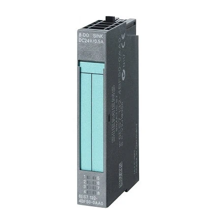
| ET200S, Electr.Module 8DO HF DC24V/0,5A | ET200S, Electr. Module 8DO DC24V/0,5A | ET200S, 8DO Sink Output DC24V/0,5A | |
| Supply voltage | |||
| Reverse voltage protection | Yes; when using the same load voltage as on the power module | Yes | Yes; when using the same correctly polarized load voltage as on the power module |
| Load voltage L+ | |||
| ● Rated value (DC) | 24 V; From power module | 24 V | 24 V; From power module |
| ● Reverse polarity protection | Yes; polarity reversal can lead to the digital outputs being connected through | Yes | Yes |
| Input current | |||
| from load voltage L+ (without load), max. | 5 mA; Per channel | 5 mA; Per channel | 5 mA |
| from backplane bus 3.3 V DC, max. | 10 mA | 10 mA | 10 mA |
| Power loss | |||
| Power loss, typ. | 1.5 W | 1.5 W | 1.5 W |
| Address area | |||
| Address space per module | |||
| ● Address space per module, max. | 1 byte | 1 byte | 1 byte |
| Digital outputs | |||
| Type of digital output | Source output (PNP, current-sourcing) | Source output (PNP, current-sourcing) | Transistor |
| Number of digital outputs | 8 | 8 | 8 |
| Short-circuit protection | Yes | Yes | Yes |
| ● Response threshold, typ. | 0.7 to 1.9 A | 1.5 A | 1.5 A |
| Limitation of inductive shutdown voltage to | L+ -(47 to 60 V) | Typ. L+ (-55 to -60 V) | Typ. 47 V |
| Controlling a digital input | Yes | Yes | Yes |
| Switching capacity of the outputs | |||
| ● on lamp load, max. | 5 W | 5 W | 5 W |
| Load resistance range | |||
| ● lower limit | 48 Ω | 48 Ω | 48 Ω |
| ● upper limit | 3 400 Ω | 3 400 Ω | 3 400 Ω |
| Output voltage | |||
| ● for signal “1”, min. | L+ (-1.0 V) | L+ (-1.0 V) | Max. 1 V |
| Output current | |||
| ● for signal “1” rated value | 0.5 A | 0.5 A | 0.5 A |
| ● for signal “1” permissible range, min. | 7 mA | 7 mA | 5 mA |
| ● for signal “1” permissible range, max. | 600 mA | 600 mA | 600 mA |
| ● for signal “0” residual current, max. | 0.3 mA | 0.3 mA | 5 µA |
| Output delay with resistive load | |||
| ● “0” to “1”, max. | 300 µs | 300 µs | 300 µs |
| ● “1” to “0”, max. | 600 µs | 600 µs | 600 µs |
| Parallel switching of two outputs | |||
| ● for uprating | No | No | No |
| ● for redundant control of a load | Yes; per module | Yes | Yes; per module |
| Switching frequency | |||
| ● with resistive load, max. | 100 Hz | 100 Hz | 100 Hz |
| ● with inductive load, max. | 2 Hz | 2 Hz | 0.5 Hz |
| ● on lamp load, max. | 10 Hz | 10 Hz | 10 Hz |
| Total current of the outputs | |||
| ● Current per module, max. | 4 A | 4 A | 4 A |
| Cable length | |||
| ● shielded, max. | 1 000 m | 1 000 m | 1 000 m |
| ● unshielded, max. | 600 m | 600 m | 600 m |
| Interrupts/diagnostics/status information | |||
| Diagnostics function | Yes | No | No |
| Diagnoses | |||
| ● Diagnostic information readable | Yes | ||
| ● Short-circuit | Yes; Module-wise | ||
| Diagnostics indication LED | |||
| ● Group error SF (red) | Yes | ||
| ● Status indicator digital output (green) | Yes; Per channel | Yes | Yes |
| Parameter | |||
| Remark | 1 byte | 3-byte parameter (not accessible for the user) | 3 byte |
| Potential separation | |||
| Potential separation digital outputs | |||
| ● between the channels | No | No | No |
| ● between the channels and backplane bus | Yes | Yes | Yes |
| Isolation | |||
| Isolation tested with | 500 V DC | 500 V DC | 500 V DC |
| Dimensions | |||
| Width | 15 mm | 15 mm | 15 mm |
| Height | 81 mm | 81 mm | 81 mm |
| Depth | 52 mm | 52 mm | 52 mm |
| Weights | |||
| Weight, approx. | 40 g | 40 g | 40 g |
| Article number | 6ES7132-4BD30-0AB0 | 6ES7132-4BD32-0AA0 | 6ES7132-4FB01-0AB0 | 6ES7132-4HB01-0AB0 | 6ES7132-4HB13-0AB0 |
| ET200S, El-Mod., 4DO HF, DC24V, 2A, 5pcs | ET200S, El-Mod., 4DO ST, DC24V, 2A, 5pcs | ET200S, Elect. Mod., 2DO, AC 230V, 5pcs | ET200S, El-Mod., 2RO. DC24VAC230V,5A,5PC | ET200S, El-Mod., 2RO,DC48V/AC230V,5A,5PC | |
| Supply voltage | |||||
| Reverse voltage protection | Yes; when using the same load voltage as on the power module | Yes; when using the same load voltage as on the power module | Yes; when using the same load voltage as on the power module | ||
| Load voltage L+ | |||||
| ● Rated value (DC) | 24 V; From power module | 24 V; From power module | 24 V; From power module | 24 V; From power module | |
| ● Reverse polarity protection | Yes; polarity reversal can lead to the digital outputs being connected through | Yes | Yes | Yes | |
| Load voltage L1 | |||||
| ● permissible range, lower limit (AC) | 24 V; From power module | ||||
| ● permissible range, upper limit (AC) | 230 V | ||||
| ● permissible frequency range, lower limit | 47 Hz | ||||
| ● permissible frequency range, upper limit | 63 Hz | ||||
| Input current | |||||
| from load voltage L+ (without load), max. | 5 mA; Per channel | 10 mA; Per channel | 30 mA | 30 mA | |
| from load voltage L1 (without load), max. | 15 mA; Per channel | ||||
| from backplane bus 3.3 V DC, max. | 10 mA | 10 mA | 18 mA | 10 mA | 10 mA |
| Power loss | |||||
| Power loss, typ. | 1.6 W | 1.6 W | 0.6 W | 0.6 W | |
| Power loss, max. | 4 W | ||||
| Address area | |||||
| Address space per module | |||||
| ● Address space per module, max. | 1 byte | 1 byte | 1 byte | 1 byte | 1 byte |
| ● with packing | 4 bit | 4 bit | 2 bit | 2 bit | 2 bit |
| Digital outputs | |||||
| Type of digital output | Transistor | Source output (PNP, current-sourcing) | Triac | Relays | Relays |
| Number of digital outputs | 4 | 4 | 2 | 2 | 2 |
| Short-circuit protection | Yes | Yes | Yes | No | No; The relay outputs must be fused externally with 6 A. When installing in a hazardous area in accordance with the National Electric Code (NEC), the fuse may only be removed using a suitable tool if the module is not in the hazardous area. |
| ● Response threshold, typ. | 5 to 10 A | 2.8 to 7.2 A | |||
| Limitation of inductive shutdown voltage to | L+ -(37 to 41V) | Typ. L+ (-55 to -60 V) | -55 to -60 V | No | No |
| Controlling a digital input | Yes | Yes | Yes; possible | Yes | Yes |
| Switching capacity of the outputs | |||||
| ● on lamp load, max. | 10 W | 100 W | |||
| Load resistance range | |||||
| ● lower limit | 12 Ω | 12 Ω | |||
| ● upper limit | 3 400 Ω | 3 400 Ω | |||
| Output voltage | |||||
| ● for signal “1”, min. | L+ (-1.0 V) | L+ (-1.0 V) | L+ (-1.5 V) | ||
| Output current | |||||
| ● for signal “1” rated value | 2 A | 2 A | 2 A | 5 A | 5 A; See data in manual |
| ● for signal “1” permissible range, min. | 7 mA | 7 mA | 0.1 mA | ||
| ● for signal “1” permissible range, max. | 2.4 A | 2.4 A | 2.2 A | ||
| ● for signal “1” minimum load current | 8 mA | 8 mA | |||
| ● for signal “0” residual current, max. | 0.5 mA | 0.1 mA | 3 mA | ||
| Output delay with resistive load | |||||
| ● “0” to “1”, max. | 250 µs | 50 µs; Typ. 45 µs | 15 ms | ||
| ● “1” to “0”, max. | 400 µs | 120 µs; Typ. 90 µs | 15 ms | ||
| Parallel switching of two outputs | |||||
| ● for uprating | No | No | No | ||
| ● for redundant control of a load | Yes; per module | Yes; per module | Yes; per module | ||
| Switching frequency | |||||
| ● with resistive load, max. | 100 Hz | 1 000 Hz | 10 Hz | 2 Hz | 2 Hz |
| ● with inductive load, max. | 2 Hz | 2 Hz; At 0.5 H | 0.5 Hz | 0.5 Hz | 0.5 Hz |
| ● on lamp load, max. | 10 Hz | 10 Hz | 1 Hz | 2 Hz | 2 Hz |
| Total current of the outputs | |||||
| ● Current per module, max. | 4 A | 4 A | 2 A; note derating data in the manual | ||
| Total current of the outputs (per group) | |||||
| horizontal installation | |||||
| — up to 50 °C, max. | 5 A; per channel | ||||
| — up to 60 °C, max. | 4 A; per channel | ||||
| vertical installation | |||||
| — up to 40 °C, max. | 5 A; per channel | ||||
| Relay outputs | |||||
| Switching capacity of contacts | |||||
| — Thermal continuous current, max. | 5 A | 5 A; See data in manual | |||
| Cable length | |||||
| ● shielded, max. | 1 000 m | 1 000 m | 1 000 m | 1 000 m | 1 000 m |
| ● unshielded, max. | 600 m | 600 m | 600 m | 600 m | 600 m |
| Interrupts/diagnostics/status information | |||||
| Diagnostics function | Yes | No | No | No | No |
| Substitute values connectable | Yes; 0/1 | Yes; 0/1 | |||
| Diagnoses | |||||
| ● Short-circuit | Yes; Module-wise | ||||
| Diagnostics indication LED | |||||
| ● Group error SF (red) | Yes; SF-LED (red) | ||||
| ● Status indicator digital output (green) | Yes; Per channel | Yes | Yes | Yes | Yes |
| Parameter | |||||
| Remark | 1 byte | 3 byte | |||
| Response to CPU/master STOP | Substitute a value/keep last value, 0/1 | Substitute a value/keep last value | Substitute a value/keep last value | ||
| Potential separation | |||||
| Potential separation digital outputs | |||||
| ● between the channels | No | No | No | Yes | Yes |
| ● between the channels and backplane bus | Yes | Yes | Yes | Yes | Yes |
| ● Between the channels and load voltage L+ | Yes | Yes | |||
| Isolation | |||||
| Isolation tested with | 500 V DC | 500 V DC | 2 500 V DC | ||
| Ambient conditions | |||||
| Altitude during operation relating to sea level | |||||
| ● Ambient air temperature-barometric pressure-altitude | Tmin … Tmax at 1 080 hPa … 795 hPa (-1 000 m … +2 000 m) // Tmin … (Tmax – 10 K) at 795 hPa … 658 hPa (+2 000 m … +3 500 m) // Tmin … (Tmax – 20 K) at 658 hPa … 540 hPa (+3 500 m … +5 000 m) | Up to max. 2 000 m | |||
| Dimensions | |||||
| Width | 15 mm | 15 mm | 15 mm | 15 mm | 15 mm |
| Height | 81 mm | 81 mm | 81 mm | 81 mm | 81 mm |
| Depth | 52 mm | 52 mm | 52 mm | 52 mm | 52 mm |
| Weights | |||||
| Weight, approx. | 40 g | 40 g | 37 g | 50 g | 50 g |