USD 215.80
Inosaki – Your Trusted Phoenix Contact Distributor
Inosaki proudly stands as one of the largest distributors of Phoenix Contact products, offering a comprehensive range of terminal blocks, interface modules, power supplies, and relays.
Series Models: PT Series, ST Series, TB Series, UT Series, and UK Series, PTV Series, UKH Series, Micro Series.
Discover industry-leading Phoenix Contact power supplies, such as:
Get Your Phoenix Contact Catalog Today
Need detailed product information? Contact us at sales@inosaki.com to request your Phoenix Contact catalog.
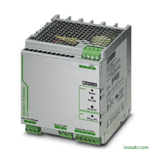
QUINT POWER power supply units – Superior system availability with SFB technology
Compact power supply units of the new QUINT POWER generation maximize the availability of your system. With the SFB technology (Selective Fuse Breaking Technology), six times the nominal current for 12 ms, even the standard power circuit-breakers can now also be triggered reliably and quickly. Faulty current paths are switched off selectively, the fault is located and important system parts continue to operate. Comprehensive diagnostics are provided through constant monitoring of output voltage and current. This preventive function monitoring visualizes critical operating modes and reports them to the control unit before an error can occur.
| Article Number | 2320830 |
|---|---|
| Width | 120 mm |
| Height | 130 mm |
| Depth | 125 mm |
| Installation distance right/left | 5 mm / 5 mm |
| Installation distance top/bottom | 50 mm / 50 mm |
| Degree of protection | IP20 |
|---|---|
| Ambient temperature (operation) | -25 °C … 70 °C (> 60 °C Derating: 2,5 %/K) |
| Ambient temperature (storage/transport) | -40 °C … 85 °C |
| Max. permissible relative humidity (operation) | ≤ 95 % (at 25 °C, non-condensing) |
| Climatic class | 3K3 (in acc. with EN 60721) |
| Degree of pollution | 2 |
| Installation height | ≤ 2000 m |
| Nominal input voltage range | 2x 400 V AC … 500 V AC |
|---|---|
| 600 V DC | |
| Input voltage range | 2x 360 V AC … 575 V AC |
| 450 V DC … 840 V DC | |
| AC frequency range | 45 Hz … 65 Hz |
| Frequency range DC | 0 Hz |
| Current consumption | 2.5 A (400 V AC) |
| 2.1 A (500 V AC) | |
| Nominal power consumption | 888 VA |
| Inrush current | < 45 A (typical) |
| Mains buffering time | typ. 20 ms (400 V AC) |
| Input fuse | 3.15 A (slow-blow, internal) |
| Recommended breaker for input protection | 10 A … 16 A (Characteristic B, C) |
| Type of protection | Transient surge protection |
| Protective circuit/component | Varistor |
| Nominal output voltage | 24 V DC ±1 % |
|---|---|
| Setting range of the output voltage (USet) | 18 V DC … 29.5 V DC (UIN ≥ 360 V AC / 480 V DC) |
| 18 V DC … 26 V DC (< 480 V DC) | |
| Nominal output current (IN) | 20 A (-25 °C … 60 °C) |
| POWER BOOST (IBoost) | 26 A (-25 °C … 40 °C permanent, UOUT = 24 V DC ) |
| Selective Fuse Breaking (ISFB) | 120 A (20 ms) |
| Derating | 60 °C … 70 °C (2.5%/K) |
| Connection in parallel | yes, for redundancy and increased capacity |
| Connection in series | yes |
| Feedback voltage resistance | < 35 V DC |
| Protection against overvoltage at the output (OVP) | < 35 V DC |
| Max. capacitive load | unlimited |
| Active current limitation | Approx. 27 A |
| Control deviation | < 1 % (change in load, static 10 % … 90 %) |
| < 2 % (change in load, dynamic 10 % … 90 %) | |
| < 0.1 % (change in input voltage ±10 %) | |
| Residual ripple | < 50 mVPP (with nominal values) |
| Output power | 480 W |
| Peak switching voltages nominal load | < 50 mVPP (20 MHz) |
| Maximum power dissipation in no-load condition | 11 W |
| Power loss nominal load max. | 51 W |
| Net weight | 2 kg |
|---|---|
| Efficiency | > 92 % (600 V DC) |
| > 90.5 % (400 V AC) | |
| MTBF (IEC 61709, SN 29500) | |
| > 860000 h (40 °C) | |
| Insulation voltage input/output | 1.5 kV AC (type test) |
| 2 kV AC (routine test) | |
| Insulation voltage input / PE | 4 kV AC (type test) |
| 1.5 kV AC (routine test) | |
| Insulation voltage output / PE | 500 V DC (routine test) |
| Degree of protection | IP20 |
| Protection class | I |
| Housing material | Steel sheet, zinc-plated |
| Mounting position | horizontal DIN rail NS 35, EN 60715 |
| Assembly instructions | alignable: PN ≥50%, 5 mm horizontally, 15 mm next to active components, 50 mm vertically alignable: PN <50%, 0 mm horizontally, 40 mm vertically top, 20 mm vertically bottom |
| Connection method | Screw connection |
|---|---|
| Conductor cross section solid min. | 0.2 mm² |
| Conductor cross section solid max. | 6 mm² |
| Conductor cross section flexible min. | 0.2 mm² |
| Conductor cross section flexible max. | 4 mm² |
| Conductor cross section AWG min. | 24 |
| Conductor cross section AWG max. | 10 |
| Stripping length | 8 mm |
| Screw thread | M3 |
| Connection method | Screw connection |
|---|---|
| Conductor cross section solid min. | 0.2 mm² |
| Conductor cross section solid max. | 6 mm² |
| Conductor cross section flexible min. | 0.2 mm² |
| Conductor cross section flexible max. | 4 mm² |
| Conductor cross section AWG min. | 12 |
| Conductor cross section AWG max. | 10 |
| Stripping length | 8 mm |
| Screw thread | M3 |
| Conductor cross section solid min. | 0.2 mm² |
|---|---|
| Conductor cross section solid max. | 6 mm² |
| Conductor cross section flexible min. | 0.2 mm² |
| Conductor cross section flexible max. | 4 mm² |
| Conductor cross section AWG min. | 24 |
| Conductor cross section AWG max. | 10 |
| Screw thread | M3 |
| Standard – Safety of transformers | EN 61558-2-17 |
|---|---|
| Standard – Electrical safety | EN 60950-1/VDE 0805 (SELV) |
| Standard – Electronic equipment for use in electrical power installations and their assembly into electrical power installations | EN 50178/VDE 0160 (PELV) |
| Standard – Safe isolation | DIN VDE 0100-410 |
| Rail applications | EN 50121-4 |
| UL approvals | UL/C-UL listed UL 508 |
|---|---|
| UL/C-UL Recognized UL 60950-1 |
| Electromagnetic compatibility | Conformance with EMC Directive 2014/30/EU |
|---|
| REACh SVHC | Lead 7439-92-1 |
|---|