| Product Name |
Specification | Model | ||||
|---|---|---|---|---|---|---|
| Number of points |
Internal I/O common |
Maximum value of load current |
I/O refreshing method |
ON/OFF response time |
||
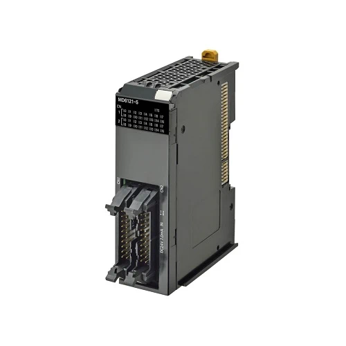
| DC Input/ Transistor Output Unit (MIL Connector, |
Outputs: 16 points Inputs: 16 points |
Outputs: NPN Inputs: For both NPN/PNP |
Outputs: 12 to 24 VDC Inputs: 24 VDCV |
Switching Synchronous I/O refreshing and Free-Run refreshing |
Outputs: 0.1 ms max./ 0.8 ms max. Inputs: 20 μs max./ 400 μs max. |
NX-MD6121-5 |
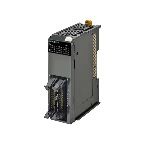
| Outputs: PNP Inputs: For both NPN/PNP |
Outputs: 24 VDC Inputs: 24 VDC |
Outputs: 0.5 ms max./ 1.0 ms max. Inputs: 20 μs max./ 400 μs max. |
NX-MD6256-5 | |||
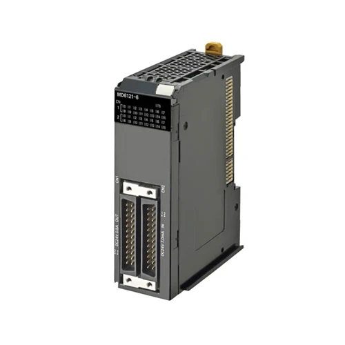
| Transistor Output Unit (Fujitsu/OTAX |
Outputs: 16 points Inputs: 16 points |
Outputs: NPN Inputs: For both NPN/PNP |
Outputs: 12 to 24 VDC Inputs: 24 VDC |
Switching Synchronous I/O refreshing and Free-Run refreshing |
Outputs: 0.1 ms max./ 0.8 ms max. Inputs: 20 μs max./ 400 μs max. |
NX-MD6121-6 |
| Item | Specification | |
|---|---|---|
| Enclosure | Mounted in a panel | |
| Grounding method | Ground to 100 Ω or less | |
| Operating environment |
Ambient operating temperature | 0 to 55°C |
| Ambient operating humidity | 10% to 95% (with no condensation or icing) | |
| Atmosphere | Must be free from corrosive gases. | |
| Ambient storage temperature | -25 to 70°C (with no condensation or icing) | |
| Altitude | 2,000 m max. | |
| Pollution degree | 2 or less: Meets IEC 61010-2-201. | |
| Noise immunity | 2 kV on power supply line (Conforms to IEC61000-4-4.) | |
| Overvoltage category | Category II: Meets IEC 61010-2-201. | |
| EMC immunity level | Zone B | |
| Vibration resistance *1 | Conforms to IEC 60068-2-6. 5 to 8.4 Hz with 3.5-mm amplitude, 8.4 to 150 Hz, acceleration of 9.8 m/s2, 100 min each in X, Y, and Z directions (10 sweeps of 10 min each = 100 min total) |
|
| Shock resistance *1 | Conforms to IEC 60068-2-27. 147 m/s2, 3 times each in X, Y, and Z directions |
|
| Applicable standards *2 | cULus: Listed (UL508) or Listed (UL 61010-2-201), ANSI/ISA 12.12.01 or UL121201, EU: EN 61131-2 or EN 61010-2-201, C-Tick or RCM, KC: KC Registration, NK, LR |
|
*1. For the Relay Output Unit, refer to the Digital Input Unit Specifications.
*2. Consult your OMRON representative for the most recent applicable standards for each model.
| Unit name | DC Input/Transistor Output Unit |
Model | NX-MD6121-5 | ||
|---|---|---|---|---|---|
| Number of points | 16 inputs/16 outputs | External connection terminals |
2 MIL connectors (20 terminals) | ||
| I/O refreshing method | Switching Synchronous I/O refreshing and Free-Run refreshing | ||||
| Output section (CN1) |
Internal I/O common |
NPN | Input section (CN2) |
Internal I/O common |
For both NPN/PNP |
| Rated voltage | 12 to 24 VDC | Rated input voltage |
24 VDC (15 to 28.8 VDC) | ||
| Operating load voltage range |
10.2 to 28.8 VDC | Input current | 7 mA typical (at 24 VDC) | ||
| Maximum value of load current |
0.5 A/point, 2 A/Unit | ON voltage/ ON current |
15 VDC min./3 mA min. (between COM and each signal) |
||
| Maximum inrush current |
4.0 A/point, 10 ms max. | OFF voltage/ OFF current |
5 VDC max./1 mA max. (between COM and each signal) |
||
| Leakage current |
0.1 mA max. | ON/OFF response time |
20 μs max./400 μs max. | ||
| Residual voltage |
1.5 V max. | Input filter time |
No filter, 0.25 ms, 0.5 ms, 1 ms (default), 2 ms, 4 ms, 8 ms, 16 ms, 32 ms, 64 ms, 128 ms, 256 ms |
||
| ON/OFF response time |
0.1 ms max./0.8 ms max. | ||||
| Indicators | TS indicator, I/O indicators |
Dimensions | 30 (W) x 100 (H) x 71 (D) | ||
| Isolation method | Photocoupler isolation | ||||
| Insulation resistance | 20 MΩ min. between isolated circuits (at 100 VDC) |
||||
| Dielectric strength | 510 VAC between isolated circuits for 1 minute at a leakage current of 5 mA max. |
||||
| I/O power supply method |
Supply from external source | ||||
| Current capacity of I/O power supply terminal |
Without I/O power supply terminals |
||||
| NX Unit power consumption |
• Connected to a CPU Unit or Communication Control Unit 1.00 W max. • Connected to a Communica- tions Coupler Unit 0.70 W max. |
||||
| Current consumption from I/O power supply |
30 mA max. | ||||
| Weight | 105 g max. | ||||
| Circuit layout |  |
||||
| Installation orientation and restrictions |
Installation orientation: • Connected to a CPU Unit or Communication Control Unit: Possible in upright installation. • Connected to a Communications Coupler Unit: Possible in 6 orientations. Restrictions: As shown in the following.  |
||||
| Terminal connection diagram |
 |
||||
| Disconnection/Short- circuit detection |
Not supported. | Protective function | Not supported. | ||
| Unit name | DC Input/Transistor Output Unit |
Model | NX-MD6256-5 | ||
|---|---|---|---|---|---|
| Number of points | 16 inputs/16 outputs | External connection terminals |
2 MIL connectors (20 terminals) | ||
| I/O refreshing method | Switching Synchronous I/O refreshing and Free-Run refreshing | ||||
| Output section (CN1) |
Internal I/O common |
PNP | Input section (CN2) |
Internal I/O common |
For both NPN/PNP |
| Rated voltage | 24 VDC | Rated input voltage |
24 VDC (15 to 28.8 VDC) | ||
| Operating load voltage range |
20.4 to 28.8 VDC | Input current | 7 mA typical (at 24 VDC) | ||
| Maximum value of load current |
0.5 A/point, 2 A/Unit | ON voltage/ ON current |
15 VDC min./3 mA min. (between COM and each signal) |
||
| Maximum inrush current |
4.0 A/point, 10 ms max. | OFF voltage/ OFF current |
5 VDC max./1 mA max. (between COM and each signal) |
||
| Leakage current |
0.1 mA max. | ON/OFF response time |
20 μs max./400 μs max. | ||
| Residual voltage |
1.5 V max. | Input filter time |
No filter, 0.25 ms, 0.5 ms, 1 ms (default), 2 ms, 4 ms, 8 ms, 16 ms, 32 ms, 64 ms, 128 ms, 256 ms |
||
| ON/OFF response time |
0.5 ms max./1.0 ms max. | ||||
| Indicators | TS indicator, I/O indicators |
Dimensions | 30 (W) x 100 (H) x 71 (D) | ||
| Isolation method | Photocoupler isolation | ||||
| Insulation resistance | 20 MΩ min. between isolated circuits (at 100 VDC) |
||||
| Dielectric strength | 510 VAC between isolated circuits for 1 minute at a leakage current of 5 mA max. |
||||
| I/O power supply method |
Supply from external source | ||||
| Current capacity of I/O power supply terminal |
Without I/O power supply terminals |
||||
| NX Unit power consumption |
• Connected to a CPU Unit or Communication Control Unit 1.10 W max. • Connected to a Communica- tions Coupler Unit 0.75 W max. |
||||
| Current consumption from I/O power supply |
40 mA max. | ||||
| Weight | 110 g max. | ||||
| Circuit layout |  |
||||
| Installation orientation and restrictions |
Installation orientation: • Connected to a CPU Unit or Communication Control Unit: Possible in upright installation. • Connected to a Communications Coupler Unit: Possible in 6 orientations. Restrictions: As shown in the following.  |
||||
| Terminal connection diagram |
 |
||||
| Disconnection/Short- circuit detection |
Not supported. | Protective function | With load short-circuit protection. |
||
DC Input/Transistor Output Unit (Fujitsu/OTAX Connector, 30 mm Width)
| Unit name | DC Input/Transistor Output Unit | Model | NX-MD6121-6 | ||
|---|---|---|---|---|---|
| Number of points | 16 inputs/16 outputs | External connection terminals |
2 Fujitsu/OTAX connectors (24 terminals) |
||
| I/O refreshing method | Switching Synchronous I/O refreshing and Free-Run refreshing | ||||
| Output section (CN1) |
Internal I/O common |
NPN | Input section (CN2) |
Internal I/O common |
For both NPN/PNP |
| Rated voltage | 12 to 24 VDC | Rated input voltage |
24 VDC (15 to 28.8 VDC) | ||
| Operating load voltage range |
10.2 to 28.8 VDC | Input current | 7 mA typical (at 24 VDC) | ||
| Maximum value of load current |
0.5 A/point, 2 A/Unit | ON voltage/ ON current |
15 VDC min./3 mA min. (between COM and each signal) |
||
| Maximum inrush current |
4.0 A/point, 10 ms max. | OFF voltage/ OFF current |
5 VDC max./1 mA max. (between COM and each signal) |
||
| Leakage current |
0.1 mA max. | ON/OFF response time |
20 μs max./400 μs max. | ||
| Residual voltage |
1.5 V max. | Input filter time |
No filter, 0.25 ms, 0.5 ms, 1 ms (default), 2 ms, 4 ms, 8 ms, 16 ms, 32 ms, 64 ms, 128 ms, 256 ms |
||
| ON/OFF response time |
0.1 ms max./0.8 ms max. | ||||
| Indicators | TS indicator, I/O indicators |
Dimensions | 30 (W) x 100 (H) x 71 (D) | ||
| Isolation method | Photocoupler isolation | ||||
| Insulation resistance | 20 MΩ min. between isolated circuits (at 100 VDC) |
||||
| Dielectric strength | 510 VAC between isolated circuits for 1 minute at a leakage current of 5 mA max. |
||||
| I/O power supply method |
Supply from external source | ||||
| Current capacity of I/O power supply terminal |
Without I/O power supply terminals |
||||
| NX Unit power consumption |
• Connected to a CPU Unit or Communication Control Unit 1.00 W max. • Connected to a Communi- cations Coupler Unit 0.70 W max. |
||||
| Current consumption from I/O power supply |
30 mA max. | ||||
| Weight | 95 g max. | ||||
| Circuit layout |  |
||||
| Installation orientation and restrictions |
Installation orientation: • Connected to a CPU Unit or Communication Control Unit: Possible in upright installation. • Connected to a Communications Coupler Unit: Possible in 6 orientations. Restrictions: As shown in the following.  |
||||
| Terminal connection diagram |
 |
||||
| Disconnection/Short- circuit detection |
Not supported. | Protective function | Not supported. | ||