Contact Us:
sales@inosaki.com

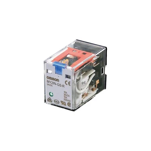
MY-GS – For Control Panel – Omron General Purpose Relays

$ 7.70$ 10.56

SKU N/A Category

Miniature Power Relays (MY-GS-R)

Category Number
of poles
Contact
structure
Plug-in (octal pins) terminals
With operation indicator
With latching lever
Standard models 2 Single MY2-GS-R MY2N-GS-R MY2IN-GS-R
4 MY4-GS-R MY4N-GS-R MY4IN-GS-R
Models with built-in diodes
for coil surge absorption
2 MY2N-D2-GS-R MY2IN-D2-GS-R
4 MY4N-D2-GS-R MY4IN-D2-GS-R
Models with built-in CR circuits
for coil surge absorption
2 MY2N-CR-GS-R MY2IN-CR-GS-R
4 MY4N-CR-GS-R MY4IN-CR-GS-R


Ordering Information

Main unit

Standard model with operation indicator

Number of poles Model Rated voltage (V)
2 MY2N-GS-R 12, 24, 48, 100/110, 110/120, 200/220, 220/240 VAC
6, 12, 24, 48, 100/110, 220 VDC
4 MY4N-GS-R 12, 24, 48, 100/110, 110/120, 200/220, 220/240 VAC
6, 12, 24, 48, 100/110, 220 VDC


Ratings

Main unit

Operating Coil

Item Rated
current (mA)
Coil
resis-
tance
(Ω)
Coil
inductance (H)
Must-
operate
voltage
Must-
release
voltage
Maxi-
mum
voltage
Power
consumption
(VA, W)
Rated voltage 50 Hz 60 Hz Armature
OFF
Armature
ON
Percentage of rated voltage
AC 12 106.5 91 46 0.17 0.33 80%
max.
*1
30%
min.
*2
110% Approx. 0.9 to
1.3 (at 60 Hz)
24 53.8 46 180 0.69 1.3
48 25.7 21.1 788 3.22 5.66
100/110 11.7/12.9 10.0/11.0 3,750 14.54 24.6
110/120 9.9/10.8 8.4/9.2 4,430 19.2 32.1
200/220 6.2/6.8 5.3/5.8 12,950 54.75 94.07
220/240 5.2/6.2 4.3/5.0 15,920 83.5 136.4
DC 6 146 (151) 41.0
(39.8)
0.17 0.33 10%
min.
*2
Approx. 0.9
12 72.7 (75) 165
(160)
0.73 1.37
24 36.3 (37.7) 662
(636)
3.2 5.72
48 17.6 (18.8) 2,725
(2,560)
10.6 21.0
100/110 8.7 (9.0)/9.6 (9.9) 11,440
(11,100)
45.6 86.2
220 3.6 60,394 362.3 452.9 Approx. 0.8


Note:
1. The rated current and coil resistance are measured at a coil temperature of 23°C with tolerances of +15%/−20% for the AC rated current and +15% for the DC coil resistance.
2. The AC coil resistance and inductance values are reference values only (at 60 Hz).
3. Operating characteristics were measured at a coil temperature of 23°C.
4. The values in parentheses for the rated currents and coil voltages of DC coils are for models with LED operation indicators.
5. The maximum voltage capacity was measured at an ambient temperature of 23°C.
*1. There is variation between products, but actual values are 80% max.
The Relay will operate if 80% or higher of the rated voltage is applied. However, to achieve the specified characteristics, apply the rated voltage to the coil.
*2. There is variation between products, but actual values are 30% minimum for AC and 10% minimum for DC. To ensure release, use a value that is lower than the specified value.

 

Contacts

2 poles 4 poles
Resistive load Inductive load
(cos φ = 0.4,
L/R = 7 ms)
Resistive load Inductive load
(cos φ = 0.4,
L/R = 7 ms)
Contact configuration DPDT 4PDT
Contact structure Single
Contact material Ag
Rated load 10 A at 250
VAC
10 A at 30
VDC
5 A at 220
VDC
5 A at 24
VDC
2 A at 220 VAC
2 A at 24 VDC
6 A at 250
VDC
6 A at 30
VDC
3 A at 220
VDC
3 A at 24
VDC
0.8 A at 220 VAC
1.5 A at 24 VDC
Electrical endurance *1 100,000
operations
500,000 operations 30,000
operations
200,000 operations
Rated carry current *2 10 A 6 A *2
Maximum contact voltage 250 VAC, 220 VDC 250 VAC, 220 VDC
Maximum contact current *2 10 A 6 A *2
Maximum switching capacity 2,500 VA
300 W
440 VA
48 W
1,500 VA
180 W
176 VA
36 W
Minimum load
(reference values) *3
1 mA at 5 VDC


*1. Rated load, switching frequency: 2,400 operations/h. Ambient temperature condition: 23°C. Duty ratio: 33%.
*2. 4 poles of 6 A is for an ambient temperature of 50°C. At an ambient temperature of 70°C, the value is 3 A.
*3. These values are guides for the switchable limits for minute load levels, such as in electronic circuits. Actual
characteristics may be different.
  These values will depend on the switching frequency, atmosphere, and expected reliability level. Confirm applicability
in the actual system under actual application conditions.


Characteristics

Main unit

2 poles 4 poles
Contact resistance *1 100 mΩ max.
Operation time *2 20 ms max.
Release time *2 20 ms max.
Maximum operating frequency Mechanical 18, 000 operations/h
Rated load 2,400 operations/h
Insulation resistance *3 1,000 MΩ min.
Dielectric strength Between coil and contacts 2,000 VAC at 50/60 Hz for 1 min.
Between contacts of different polarity 2,000 VAC at 50/60 Hz for 1 min.
Between contacts of the same polarity 1,000 VAC at 50/60 Hz for 1 min.
Vibration resistance Destruction 10 to 55 to 10 Hz, Double amplitude: 1.0 mm
Malfunction 10 to 55 to 10 Hz, Double amplitude: 1.0 mm
Shock resistance Destruction 1,000 m/s2 (approx. 100 G)
Malfunction 200 m/s2 (Approx. 20 G)
Mechanical endurance 50,000,000 operations (switching frequency: 18,000 operations/h)
Ambient operating temperature Standard models: -55 to 70°C (with no icing or condensation)
Models with LED operation indicators: -40 to 70°C (with no icing or condensation)
Ambient humidity 5% to 85%
Weight Approx. 35 g


Note: The above values are initial values.
*1. Measurement conditions: 1 A at 5 VDC using the voltage drop method.
*2. Measurement conditions: With rated operating power applied, not including contact bounce time.
*3. Measurement conditions: For 500 VDC applied to the same location as for dielectric strength measurement.

Related Products

SICK_Inductive Proximity Sensors_IM05-0B8PO-ZT1
AFPX-C14P
$ 178.20 - $ 776.60
Festo_Guided cylinders_DGSL-6-20-P1A_543922
SCHNEIDER_RSL Interface Relay,24 V AC-DC-6A-Spring Wire
SICK_sensor_Photoelectric_sensor_W4S-3 Inox Hygiene_WSE4S-3E3130H
PEPPERLFUCHS_Inductive Sensors_NBN15-30GM50-E2-V1_1
Select your currency