USD 357.24 – USD 418.34Price range: USD 357.24 through USD 418.34
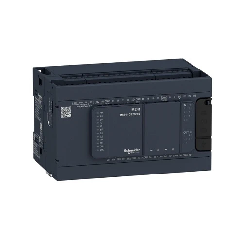
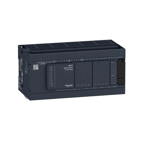
This product is part of the Modicon M241 range, an offer of logic controllers for performance demanding applications. This logic controller provides 14 discrete, 8 fast inputs, 6 relay, 4 transistor, 4 fast outputs with transistor, relay output. It has a rated supply voltage of 100V to 240V AC, an output voltage of 5V to 125V DC or 5V to 250V AC for relay, 24V DC for transistor, and an output current of 2A for relay, 0.1A for fast output, 0.5A for transistor. This product enables to build application intuitively as never before due to an organised screen design. Integrated connections are USB port with mini B USB 2.0 connector, non isolated serial link 1 with RJ45 connector and RS232/RS485 interface and non isolated serial link 2 with removable screw terminal block connector and RS485 interface. It is a Modicon M241 controller with 8MB for program, 64MB for system memory RAM, 128MB built-in flash memory for backup of user programs and a SD card memory capacity of 16GB. It is an IP20 rated product. Its dimensions are 150mm (Width) x 95mm (Depth) x 90mm (Height). It weighs 0.53kg. The Modicon M241 logic controllers are designed for high-performance compact machines incorporating speed and position control functions. This product is certified by CE, IACS E10, RCM, CSA, CULus. It meets ANSI/ISA 12-12-01, CSA C22.2 No 142, CSA C22.2 No 213, EN/IEC 61131-22007, marine specification (LR, ABS, DNV, GL), UL 1604 and UL 508 standards. It supports DIN rail mount. Achieve benchmark performance while increasing profitability with the Modicon M241 through intuitive machine programming with EcoStruxure Machine Expert, ready-to-use applications and function blocks.
| Main | ||
| Part Number | TM241C24R | TM241C40R |
| Range of product | Modicon M241 | Modicon M241 |
| Product or component type | Logic controller | Logic controller |
| [Us] rated supply voltage | 100…240 V AC | 100…240 V AC |
| Discrete input number | 14, discrete input 8 fast input conforming to IEC 61131-2 Type 1 | 24, discrete input 8 fast input conforming to IEC 61131-2 Type 1 |
| Discrete output type | Transistor | Relay |
| Relay | Transistor | |
| Discrete output number | 6 relay | 4 transistor 4 fast output |
| 4 transistor 4 fast output | 12 relay | |
| Discrete output voltage | 5…125 V DC for relay output | 5…125 V DC for relay output |
| 5…250 V AC for relay output | 5…250 V AC for relay output | |
| 24 V DC for transistor output | 24 V DC for transistor output | |
| Discrete output current | 2 A for relay output (Q4…Q9) | 0.1 A for fast output (PTO mode) (TR0…TR3) |
| 0.1 A for fast output (PTO mode) (TR0…TR3) | 2 A for relay output (Q4…Q15) | |
| 0.5 A for transistor output (TR0…TR3) | 0.5 A for transistor output (TR0…TR3) | |
| Complementary | ||
| Discrete I/O number | 24 | 40 |
| Maximum number of I/O expansion module | 7 (local I/O-Architecture) | 7 (local I/O-Architecture) |
| 14 (remote I/O-Architecture) | 14 (remote I/O-Architecture) | |
| Supply voltage limits | 85…264 V | 85…264 V |
| Network frequency | 50/60 Hz | 50/60 Hz |
| Discrete input logic | Sink or source | Sink or source |
| Discrete input voltage | 24 V | 24 V |
| Discrete input voltage type | DC | DC |
| Voltage state 1 guaranteed | >= 15 V for input | >= 15 V for input |
| Voltage state 0 guaranteed | <= 5 V for input | <= 5 V for input |
| Discrete input current | 5 mA for input | 7 mA for input |
| Input impedance | 4.7 kOhm for input | 4.7 kOhm for input |
| Response time | 50 µs turn-on, I0…I13 terminal(s) for input | 50 µs turn-on, I0…I15 terminal(s) for input |
| Configurable filtering time | 1 µs for fast input | 1 µs for fast input |
| Discrete output logic | Positive logic (source) | Positive logic (source) |
| Output voltage limits | 125 V DC relay output | 125 V DC relay output |
| 30 V DC transistor output | 30 V DC transistor output | |
| 277 V AC relay output | 277 V AC relay output | |
| Maximum output frequency | 1 kHz for transistor output | 1 kHz for transistor output |
| 20 kHz for fast output (PWM mode) | 20 kHz for fast output (PWM mode) | |
| 100 kHz for fast output (PLS mode) | 100 kHz for fast output (PLS mode) | |
| Accuracy | +/- 0.1 % at 0.02…0.1 kHz for fast output | +/- 0.1 % at 0.02…0.1 kHz for fast output |
| +/- 1 % at 0.1…1 kHz for fast output | ||
| Protection type | Short-circuit protection for transistor output | Short-circuit protection for transistor output |
| Short-circuit and overload protection with automatic reset for transistor output | Short-circuit and overload protection with automatic reset for transistor output | |
| Reverse polarity protection for transistor output | Reverse polarity protection for transistor output | |
| Without protection for relay output | Without protection for relay output | |
| Reset time | 10 ms automatic reset output | 10 ms automatic reset output |
| 12 s automatic reset fast output | 12 s automatic reset fast output | |
| Memory capacity | 8 MB for program | 8 MB for program |
| 64 MB for system memory RAM | 64 MB for system memory RAM | |
| Data backed up | 128 MB built-in flash memory for backup of user programs | 128 MB built-in flash memory for backup of user programs |
| Data storage equipment | <= 16 GB SD card (optional) | <= 16 GB SD card (optional) |
| Battery type | BR2032 lithium non-rechargeable, battery life: 4 year(s) | BR2032 lithium non-rechargeable, battery life: 4 year(s) |
| Backup time | 2 years at 25 °C | 2 years at 25 °C |
| Execution time for 1 KInstruction | 0.3 ms for event and periodic task | 0.3 ms for event and periodic task |
| 0.7 ms for other instruction | 0.7 ms for other instruction | |
| Application structure | 4 cyclic master tasks | 4 cyclic master tasks |
| 3 cyclic master tasks + 1 freewheeling task | 3 cyclic master tasks + 1 freewheeling task | |
| 8 external event tasks | 8 external event tasks | |
| 8 event tasks | 8 event tasks | |
| Realtime clock | With | With |
| Clock drift | <= 60 s/month at 25 °C | <= 60 s/month at 25 °C |
| Positioning functions | PTO function 4 channel(s) (positioning frequency: 100 kHz) | PTO function 4 channel(s) (positioning frequency: 100 kHz) |
| Counting input number | 4 fast input (HSC mode) at 200 kHz | 4 fast input (HSC mode) at 200 kHz |
| 14 standard input at 1 kHz | 14 standard input at 1 kHz | |
| Control signal type | A/B at 100 kHz for fast input (HSC mode) | A/B at 100 kHz for fast input (HSC mode) |
| Pulse/direction at 200 kHz for fast input (HSC mode) | Pulse/direction at 200 kHz for fast input (HSC mode) | |
| Single phase at 200 kHz for fast input (HSC mode) | Single phase at 200 kHz for fast input (HSC mode) | |
| Integrated connection type | Non isolated serial link serial 1 with RJ45 connector and RS232/RS485 interface | Non isolated serial link serial 1 with RJ45 connector and RS232/RS485 interface |
| Non isolated serial link serial 2 with removable screw terminal block connector and RS485 interface | Non isolated serial link serial 2 with removable screw terminal block connector and RS485 interface | |
| USB port with mini B USB 2.0 connector | USB port with mini B USB 2.0 connector | |
| Supply | (Serial 1)serial link supply: 5 V, <200 mA | (Serial 1)serial link supply: 5 V, <200 mA |
| Transmission rate | 1.2…115.2 kbit/s (115.2 kbit/s by default) for bus length of 15 m for RS485 | 1.2…115.2 kbit/s (115.2 kbit/s by default) for bus length of 15 m for RS485 |
| 1.2…115.2 kbit/s (115.2 kbit/s by default) for bus length of 3 m for RS232 | 1.2…115.2 kbit/s (115.2 kbit/s by default) for bus length of 3 m for RS232 | |
| 480 Mbit/s for bus length of 3 m for USB | 480 Mbit/s for bus length of 3 m for USB | |
| Communication port protocol | Non isolated serial link: Modbus master/slave | Non isolated serial link: Modbus master/slave |
| Local signalling | 1 LED (green) for PWR | 1 LED (green) for PWR |
| 1 LED (green) for RUN | 1 LED (green) for RUN | |
| 1 LED (red) for module error (ERR) | 1 LED (red) for module error (ERR) | |
| 1 LED (red) for I/O error (I/O) | 1 LED (red) for I/O error (I/O) | |
| 1 LED (green) for SD card access (SD) | 1 LED (green) for SD card access (SD) | |
| 1 LED (red) for BAT | 1 LED (red) for BAT | |
| 1 LED (green) for SL1 | 1 LED (green) for SL1 | |
| 1 LED (green) for SL2 | 1 LED (green) for SL2 | |
| 1 LED (red) for bus fault on TM4 (TM4) | 1 LED (red) for bus fault on TM4 (TM4) | |
| 1 LED per channel (green) for I/O state | 1 LED per channel (green) for I/O state | |
| Electrical connection | Removable screw terminal blockfor inputs and outputs (pitch 5.08 mm) | Removable screw terminal blockfor inputs and outputs (pitch 5.08 mm) |
| removable screw terminal blockfor connecting the 24 V DC power supply (pitch 5.08 mm) | removable screw terminal blockfor connecting the 24 V DC power supply (pitch 5.08 mm) | |
| Maximum cable distance between devices | Unshielded cable: <50 m for input | Unshielded cable: <50 m for input |
| Shielded cable: <10 m for fast input | Shielded cable: <10 m for fast input | |
| Unshielded cable: <50 m for output | Unshielded cable: <50 m for output | |
| Shielded cable: <3 m for fast output | Shielded cable: <3 m for fast output | |
| Insulation | Between supply and internal logic at 500 V AC | Between supply and internal logic at 500 V AC |
| Non-insulated between supply and ground | Non-insulated between supply and ground | |
| Marking | CE | CE |
| Sensor power supply | 24 V DC at 400 mA supplied by the controller | 24 V DC at 400 mA supplied by the controller |
| Surge withstand | 2 kV power lines (AC) common mode conforming to EN/IEC 61000-4-5 | 2 kV power lines (AC) common mode conforming to EN/IEC 61000-4-5 |
| 2 kV relay output common mode conforming to EN/IEC 61000-4-5 | 2 kV relay output common mode conforming to EN/IEC 61000-4-5 | |
| 1 kV shielded cable common mode conforming to EN/IEC 61000-4-5 | 1 kV shielded cable common mode conforming to EN/IEC 61000-4-5 | |
| 1 kV power lines (AC) differential mode conforming to EN/IEC 61000-4-5 | 1 kV power lines (AC) differential mode conforming to EN/IEC 61000-4-5 | |
| 1 kV relay output differential mode conforming to EN/IEC 61000-4-5 | 1 kV relay output differential mode conforming to EN/IEC 61000-4-5 | |
| 1 kV input common mode conforming to EN/IEC 61000-4-5 | 1 kV input common mode conforming to EN/IEC 61000-4-5 | |
| 1 kV transistor output common mode conforming to EN/IEC 61000-4-5 | 1 kV transistor output common mode conforming to EN/IEC 61000-4-5 | |
| Mounting support | Top hat type TH35-15 rail conforming to IEC 60715 | Top hat type TH35-15 rail conforming to IEC 60715 |
| Top hat type TH35-7.5 rail conforming to IEC 60715 | Top hat type TH35-7.5 rail conforming to IEC 60715 | |
| plate or panel with fixing kit | plate or panel with fixing kit | |
| Height | 90 mm | 90 mm |
| Depth | 95 mm | 95 mm |
| Width | 150 mm | 190 mm |
| Product weight | 0.53 kg | 0.62 kg |
| Environment | ||
| Standards | ANSI/ISA 12-12-01 | ANSI/ISA 12-12-01 |
| CSA C22.2 No 142 | CSA C22.2 No 142 | |
| CSA C22.2 No 213 | CSA C22.2 No 213 | |
| EN/IEC 61131-2:2007 | EN/IEC 61131-2:2007 | |
| Marine specification (LR, ABS, DNV, GL) | Marine specification (LR, ABS, DNV, GL) | |
| UL 1604 | UL 1604 | |
| UL 508 | UL 508 | |
| Product certifications | IACS E10 | RCM |
| RCM | CSA | |
| cULus | cULus | |
| CSA | IACS E10 | |
| Resistance to electrostatic discharge | 8 kV in air conforming to EN/IEC 61000-4-2 | 8 kV in air conforming to EN/IEC 61000-4-2 |
| 4 kV on contact conforming to EN/IEC 61000-4-2 | 4 kV on contact conforming to EN/IEC 61000-4-2 | |
| Resistance to electromagnetic fields | 10 V/m 80 MHz…1 GHz conforming to EN/IEC 61000-4-3 | 10 V/m 80 MHz…1 GHz conforming to EN/IEC 61000-4-3 |
| 3 V/m 1.4 GHz…2 GHz conforming to EN/IEC 61000-4-3 | 3 V/m 1.4 GHz…2 GHz conforming to EN/IEC 61000-4-3 | |
| 1 V/m 2 GHz…3 GHz conforming to EN/IEC 61000-4-3 | 1 V/m 2 GHz…3 GHz conforming to EN/IEC 61000-4-3 | |
| Resistance to fast transients | 2 kV (power lines) conforming to EN/IEC 61000-4-4 | 2 kV (power lines) conforming to EN/IEC 61000-4-4 |
| 2 kV (relay output) conforming to EN/IEC 61000-4-4 | 2 kV (relay output) conforming to EN/IEC 61000-4-4 | |
| 1 kV (serial link) conforming to EN/IEC 61000-4-4 | 1 kV (serial link) conforming to EN/IEC 61000-4-4 | |
| 1 kV (input) conforming to EN/IEC 61000-4-4 | 1 kV (input) conforming to EN/IEC 61000-4-4 | |
| 1 kV (transistor output) conforming to EN/IEC 61000-4-4 | 1 kV (transistor output) conforming to EN/IEC 61000-4-4 | |
| Resistance to conducted disturbances | 10 V 0.15…80 MHz conforming to EN/IEC 61000-4-6 | 10 V 0.15…80 MHz conforming to EN/IEC 61000-4-6 |
| 3 V 0.1…80 MHz conforming to Marine specification (LR, ABS, DNV, GL) | 3 V 0.1…80 MHz conforming to Marine specification (LR, ABS, DNV, GL) | |
| 10 V spot frequency (2, 3, 4, 6.2, 8.2, 12.6, 16.5, 18.8, 22, 25 MHz) conforming to Marine specification (LR, ABS, DNV, GL) | 10 V spot frequency (2, 3, 4, 6.2, 8.2, 12.6, 16.5, 18.8, 22, 25 MHz) conforming to Marine specification (LR, ABS, DNV, GL) | |
| Electromagnetic emission | Conducted emissions – test level: 120…69 dBµV/m QP ( power lines) at 10…150 kHz conforming to EN/IEC 55011 | Conducted emissions – test level: 120…69 dBµV/m QP ( power lines) at 10…150 kHz conforming to EN/IEC 55011 |
| Conducted emissions – test level: 63 dBμV/m QP ( power lines) at 1.5…30 MHz conforming to EN/IEC 55011 | Conducted emissions – test level: 63 dBμV/m QP ( power lines) at 1.5…30 MHz conforming to EN/IEC 55011 | |
| Conducted emissions – test level: 79 dBμV/m QP/66 dBμV/m AV ( power lines) at 0.15…0.5 MHz conforming to EN/IEC 55011 | Conducted emissions – test level: 79 dBμV/m QP/66 dBμV/m AV ( power lines) at 0.15…0.5 MHz conforming to EN/IEC 55011 | |
| Conducted emissions – test level: 73 dBμV/m QP/60 dBμV/m AV ( power lines) at 0.5…300 MHz conforming to EN/IEC 55011 | Conducted emissions – test level: 73 dBμV/m QP/60 dBμV/m AV ( power lines) at 0.5…300 MHz conforming to EN/IEC 55011 | |
| Radiated emissions – test level: 40 dBμV/m QP class A ( 10 m) at 30…230 MHz conforming to EN/IEC 55011 | Radiated emissions – test level: 40 dBμV/m QP class A ( 10 m) at 30…230 MHz conforming to EN/IEC 55011 | |
| Conducted emissions – test level: 79…63 dBμV/m QP ( power lines) at 150…1500 kHz conforming to EN/IEC 55011 | Conducted emissions – test level: 79…63 dBμV/m QP ( power lines) at 150…1500 kHz conforming to EN/IEC 55011 | |
| Radiated emissions – test level: 47 dBμV/m QP class A ( 10 m) at 230…1000 MHz conforming to EN/IEC 55011 | Radiated emissions – test level: 47 dBμV/m QP class A ( 10 m) at 230…1000 MHz conforming to EN/IEC 55011 | |
| Immunity to microbreaks | 10 ms | 10 ms |
| Ambient air temperature for operation | -10…50 °C (vertical installation) | -10…50 °C (vertical installation) |
| -10…55 °C (horizontal installation) | -10…55 °C (horizontal installation) | |
| Ambient air temperature for storage | -25…70 °C | -25…70 °C |
| Relative humidity | 10…95 %, without condensation (in operation) | 10…95 %, without condensation (in operation) |
| 10…95 %, without condensation (in storage) | 10…95 %, without condensation (in storage) | |
| IP degree of protection | IP20 with protective cover in place | IP20 with protective cover in place |
| Pollution degree | 2 | 2 |
| Operating altitude | 0…2000 m | 0…2000 m |
| Storage altitude | 0…3000 m | 0…3000 m |
| Vibration resistance | 3.5 mm at 5…8.4 Hz on symmetrical rail | 3.5 mm at 5…8.4 Hz on symmetrical rail |
| 3 gn at 8.4…150 Hz on symmetrical rail | 3 gn at 8.4…150 Hz on symmetrical rail | |
| 3.5 mm at 5…8.4 Hz on panel mounting | 3.5 mm at 5…8.4 Hz on panel mounting | |
| 3 gn at 8.4…150 Hz on panel mounting | 3 gn at 8.4…150 Hz on panel mounting | |
| Shock resistance | 15 gn for 11 ms | 15 gn for 11 ms |
| Packing Units | ||
| Unit Type of Package 1 | PCE | PCE |
| Number of Units in Package 1 | 1 | 1 |
| Package 1 Height | 11.253 cm | 12.8 cm |
| Package 1 Width | 13.231 cm | 11.46 cm |
| Package 1 Length | 18.673 cm | 22.61 cm |
| Package 1 Weight | 750.0 g | 930 g |
| Unit Type of Package 2 | S03 | S03 |
| Number of Units in Package 2 | 8 | 6 |
| Package 2 Height | 30 cm | 30 cm |
| Package 2 Width | 30 cm | 30 cm |
| Package 2 Length | 40 cm | 40 cm |
| Package 2 Weight | 6.91 kg | 6.22 kg |
| Unit Type of Package 3 | P06 | P12 |
| Number of Units in Package 3 | 64 | 144 |
| Package 3 Height | 75.0 cm | 80.0 cm |
| Package 3 Width | 60.0 cm | 105.0 cm |
| Package 3 Length | 80.0 cm | 125.0 cm |
| Package 3 Weight | 60.64 kg | 136 kg |