USD 316.34 – USD 1,290.10Price range: USD 316.34 through USD 1,290.10
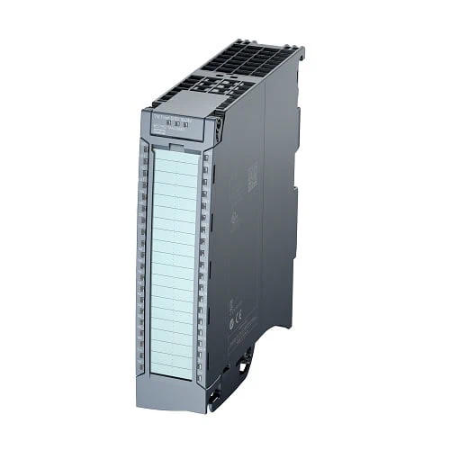
Digital output modules switch 24 V DC or 230 V AC voltages in the plant and thus transfer internal signals from the PLC to the plant. Solenoid valves, DC contactors, and indicator lights can be connected.
High Feature output modules feature configurable parameters and diagnostic functions and can thus be freely adapted to the respective process requirements.
Low-cost 25 mm wide output modules do not have settable parameters or diagnostic functions and can therefore be integrated very easily into the engineering. They are recommended for use in locations where only very few input channels are necessary or under conditions of use in which a high number of channels must be implemented in a very limited space.
Both module types can be used side by side in one station as required. Standardized features and shared system accessories guarantee easy handling.
The following digital output modules with a width of 35 mm are available:
The following digital output modules with a width of 25 mm are available:
| Article number | 6ES7522-1BH01-0AB0 | 6ES7522-1BL01-0AB0 | 6ES7522-1BF00-0AB0 | 6ES7522-5EH00-0AB0 | |
| S7-1500, DQ 16x24V DC/0.5A HF | S7-1500, DQ 32x24VDC/0.5A HF | S7-1500, DQ 8x24VDC/2A HF | S7-1500, DQ 16×24…48VUC/125VDC/0.5A ST | ||
| General information | |||||
| Product type designation | DQ 16x24VDC/0.5A HF | DQ 32x24VDC/0.5A HF | DQ 8x24VDC/2A HF | DQ 16×24 … 48 V UC/125 V DC/0.5 A ST | |
| HW functional status | From FS02 | From FS02 | FS03 | FS02 | |
| Firmware version | V1.1.0 | V1.1.0 | V2.2.0 | V1.0.0 | |
| ● FW update possible | Yes | Yes | Yes | ||
| Product function | |||||
| ● I&M data | Yes; I&M0 to I&M3 | Yes; I&M0 to I&M3 | Yes; I&M0 to I&M3 | Yes; I&M0 to I&M3 | |
| ● Isochronous mode | Yes | Yes | No | No | |
| ● Prioritized startup | Yes | Yes | Yes | Yes | |
| Engineering with | |||||
| ● STEP 7 TIA Portal configurable/integrated from version | V13 SP1 / – | V13 SP1 / – | V13 SP1 / – | V13 SP1 / – | |
| ● STEP 7 configurable/integrated from version | V5.5 SP3 / – | V5.5 SP3 / – | V5.5 SP3 / – | V5.5 SP3 / – | |
| ● PROFIBUS from GSD version/GSD revision | V1.0 / V5.1 | V1.0 / V5.1 | V1.0 / V5.1 | V1.0 / V5.1 | |
| ● PROFINET from GSD version/GSD revision | V2.3 / – | V2.3 / – | V2.3 / – | V2.3 / – | |
| Operating mode | |||||
| ● DQ | Yes | Yes | Yes | Yes | |
| ● DQ with energy-saving function | No | No | Yes; with an application | No | |
| ● PWM | No | No | Yes; FS02 and FW V2.1.0 or higher; two outputs can be operated with max. 500 Hz PWM | No | |
| ● Cam control (switching at comparison values) | No | No | No | No | |
| ● Oversampling | No | No | No | No | |
| ● MSO | Yes | Yes | Yes | Yes | |
| ● Integrated operating cycle counter | Yes | Yes | Yes | No | |
| Supply voltage | |||||
| Rated value (DC) | 24 V | 24 V | 24 V | ||
| permissible range, lower limit (DC) | 19.2 V | 19.2 V | 19.2 V | ||
| permissible range, upper limit (DC) | 28.8 V | 28.8 V | 28.8 V | ||
| Reverse polarity protection | Yes; through internal protection with 7 A per group | Yes; through internal protection with 7 A per group | Yes; through internal protection with 10 A per group | ||
| Input current | |||||
| Current consumption, max. | 30 mA | 60 mA | 40 mA; 20 mA per group, no output is activated. | ||
| output voltage / header | |||||
| Rated value (DC) | 24 V | 24 V | 24 V | 24 V; 48 V, 125 V | |
| Rated value (AC) | 24 V; 48 V (50 – 60 Hz) | ||||
| Power | |||||
| Power available from the backplane bus | 1.1 W | 1.1 W | 0.9 W | 2 W | |
| Power loss | |||||
| Power loss, typ. | 2 W | 3.5 W | 5.6 W; 6.8 W for PWM operation | 3.8 W | |
| Digital outputs | |||||
| Type of digital output | Transistor | Transistor | Transistor | Transistor | |
| Number of digital outputs | 16 | 32 | 8 | 16 | |
| Current-sinking | Yes | ||||
| Current-sourcing | Yes | Yes | Yes | Yes | |
| Digital outputs, parameterizable | Yes | Yes | Yes | Yes | |
| Short-circuit protection | Yes; Clocked electronically | Yes; Clocked electronically | Yes | ||
| ● Response threshold, typ. | 1 A | 1 A | 3 A | ||
| Limitation of inductive shutdown voltage to | L+ (-53 V) | L+ (-53 V) | -17 V | 200 V (suppressor diode) | |
| Controlling a digital input | Yes | Yes | Yes | Yes | |
| Digital output functions, parameterizable | |||||
| ● Freely usable digital output | Yes | ||||
| ● PWM output | Yes; FS02 and FW V2.1.0 or higher | ||||
| — Number, max. | 2 | ||||
| — Cycle duration, parameterizable | Yes; 2 … 100 ms continuous | ||||
| — ON period, min. | 0 % | ||||
| — ON period, max. | 100 % | ||||
| — Resolution of the duty cycle | 0.1 % | ||||
| — Minimum pulse duration | 300 µs | ||||
| Switching capacity of the outputs | |||||
| ● with resistive load, max. | 0.5 A | 0.5 A | 0.5 A | ||
| ● on lamp load, max. | 5 W | 5 W | 10 W | 40 W; At 125 V DC, 10 W at 48 V UC, 5 W at 24 V UC | |
| Load resistance range | |||||
| ● lower limit | 48 Ω | 48 Ω | 12 Ω | ||
| ● upper limit | 12 kΩ | 12 kΩ | 4 kΩ | ||
| Output voltage | |||||
| ● for signal “1”, min. | L+ (-0.8 V) | L+ (-0.8 V) | L+ (-0.8 V) | L+ (-1.0 V) | |
| Output current | |||||
| ● for signal “1” rated value | 0.5 A | 0.5 A | 2 A | 0.5 A | |
| ● for signal “1” permissible range, max. | 0.5 A | 0.5 A | 2.4 A; note derating specification for PWM operation | 0.6 A | |
| ● for signal “0” residual current, max. | 0.5 mA | 0.5 mA | 0.5 mA | ||
| Output delay with resistive load | |||||
| ● “0” to “1”, typ. | 80 µs | ||||
| ● “0” to “1”, max. | 100 µs | 100 µs | 100 µs | 5 ms | |
| ● “1” to “0”, typ. | 300 µs | ||||
| ● “1” to “0”, max. | 500 µs | 500 µs | 500 µs | 5 ms | |
| Parallel switching of two outputs | |||||
| ● for logic links | Yes | Yes | Yes | Yes | |
| ● for uprating | No | No | No | No | |
| ● for redundant control of a load | Yes | Yes | Yes | Yes | |
| Switching frequency | |||||
| ● with resistive load, max. | 100 Hz | 100 Hz | 100 Hz; With PWM operation: 500 Hz | 25 Hz | |
| ● with inductive load, max. | 0.5 Hz; According to IEC 60947-5-1, DC-13 | 0.5 Hz; According to IEC 60947-5-1, DC-13 | 0.5 Hz; According to IEC 60947-5-1, DC-13; max. 500 Hz with PWM operation only with external circuit; see additional description in the manual | 0.5 Hz | |
| ● on lamp load, max. | 10 Hz | 10 Hz | 10 Hz | 10 Hz | |
| Total current of the outputs | |||||
| ● Current per channel, max. | 0.5 A; see additional description in the manual | 0.5 A; see additional description in the manual | 2 A; see additional description in the manual | 0.5 A | |
| ● Current per group, max. | 4 A; see additional description in the manual | 4 A; see additional description in the manual | 8 A; see additional description in the manual | 0.5 A | |
| ● Current per module, max. | 8 A; see additional description in the manual | 16 A; see additional description in the manual | 16 A; see additional description in the manual | 8 A | |
| Cable length | |||||
| ● shielded, max. | 1 000 m | 1 000 m | 1 000 m | 1 000 m | |
| ● unshielded, max. | 600 m | 600 m | 600 m | 600 m | |
| Isochronous mode | |||||
| Execution and activation time (TCO), min. | 70 µs | 70 µs | |||
| Bus cycle time (TDP), min. | 250 µs | 250 µs | |||
| Interrupts/diagnostics/status information | |||||
| Diagnostics function | Yes | Yes | Yes | No | |
| Substitute values connectable | Yes | Yes | Yes | Yes | |
| Alarms | |||||
| ● Diagnostic alarm | Yes | Yes | Yes | No | |
| ● Maintenance interrupt | Yes | Yes | Yes | No | |
| Diagnoses | |||||
| ● Monitoring the supply voltage | Yes | Yes | Yes | No | |
| ● Wire-break | Yes | Yes | No | No | |
| ● Short-circuit | Yes | Yes | Yes | No | |
| ● Group error | Yes | Yes | Yes | ||
| Diagnostics indication LED | |||||
| ● RUN LED | Yes; green LED | Yes; green LED | Yes; green LED | Yes; green LED | |
| ● ERROR LED | Yes; red LED | Yes; red LED | Yes; red LED | Yes; red LED | |
| ● MAINT LED | Yes; Yellow LED | Yes; Yellow LED | Yes; Yellow LED | ||
| ● Monitoring of the supply voltage (PWR-LED) | Yes; green LED | Yes; green LED | Yes; green LED | No | |
| ● Channel status display | Yes; green LED | Yes; green LED | Yes; green LED | Yes; green LED | |
| ● for channel diagnostics | Yes; red LED | Yes; red LED | Yes; red LED | No | |
| ● for module diagnostics | Yes; red LED | Yes; red LED | Yes; red LED | Yes; red LED | |
| Potential separation | |||||
| Potential separation channels | |||||
| ● between the channels | No | No | No | Yes | |
| ● between the channels, in groups of | 8 | 8 | 4 | 1 | |
| ● between the channels and backplane bus | Yes | Yes | Yes | Yes | |
| Permissible potential difference | |||||
| between different circuits | 125 V DC/48 V AC | ||||
| Isolation | |||||
| Isolation tested with | 707 V DC (type test) | 707 V DC (type test) | 707 V DC (type test) | 2 000 V DC | |
| Standards, approvals, certificates | |||||
| Suitable for safety functions | No | No | No | No | |
| Suitable for safety-related tripping of standard modules | Yes; From FS02 | Yes; From FS02 | Yes; From FS03 | Yes; From FS02 | |
| Highest safety class achievable for safety-related tripping of standard modules | |||||
| ● Performance level according to ISO 13849-1 | PL d | PL d | PL d | PL d | |
| ● Category according to ISO 13849-1 | Cat. 3 | Cat. 3 | Cat. 3 | Cat. 3 | |
| ● SIL acc. to IEC 62061 | SIL 2 | SIL 2 | SIL 2 | SIL 2 | |
| Ambient conditions | |||||
| Ambient temperature during operation | |||||
| ● horizontal installation, min. | -30 °C; From FS03 | -30 °C; From FS03 | 0 °C | ||
| ● horizontal installation, max. | 60 °C | 60 °C | 60 °C | ||
| ● vertical installation, min. | -30 °C; From FS03 | -30 °C; From FS03 | 0 °C | ||
| ● vertical installation, max. | 40 °C | 40 °C | 40 °C | ||
| Altitude during operation relating to sea level | |||||
| ● Installation altitude above sea level, max. | 5 000 m; Restrictions for installation altitudes > 2 000 m, see manual | 5 000 m; Restrictions for installation altitudes > 2 000 m, see manual | 5 000 m; Restrictions for installation altitudes > 2 000 m, see manual | ||
| Dimensions | |||||
| Width | 35 mm | 35 mm | 35 mm | 35 mm | |
| Height | 147 mm | 147 mm | 147 mm | 147 mm | |
| Depth | 129 mm | 129 mm | 129 mm | 129 mm | |
| Weights | |||||
| Weight, approx. | 230 g | 280 g | 240 g | 230 g | |
| Article number | 6ES7522-5HF00-0AB0 | 6ES7522-5HH00-0AB0 | 6ES7522-5FF00-0AB0 | 6ES7522-5FH00-0AB0 | |
| S7-1500, DQ 8x230VAC/5A ST (Relay) | S7-1500, DQ 16x230VAC/2A ST (Relay) | S7-1500, DQ 8x230VAC/2A ST (Triac) | S7-1500, DQ 16x230VAC/1A ST (Triac) | ||
| General information | |||||
| Product type designation | DQ 8×230 V AC/5 A ST (relay) | DQ 16x 230 V AC/2 A ST (relay) | DQ 8×230 V AC/2A ST (triac) | DQ 16x230VAC/1A ST (Triac) | |
| HW functional status | From FS02 | FS01 | From FS01 | From FS01 | |
| Firmware version | V2.1.0 | V1.1.0 | V2.2.0 | V 1.2.0 | |
| ● FW update possible | Yes | Yes | Yes | Yes | |
| Product function | |||||
| ● I&M data | Yes; I&M0 to I&M3 | Yes; I&M0 to I&M3 | Yes; I&M0 to I&M3 | Yes; I&M0 to I&M3 | |
| ● Isochronous mode | No | No | No | No | |
| ● Prioritized startup | Yes | Yes | Yes | Yes | |
| Engineering with | |||||
| ● STEP 7 TIA Portal configurable/integrated from version | V12 / V12 | V13 SP1 / – | V12 / V12 | V13 SP1 / – | |
| ● STEP 7 configurable/integrated from version | V5.5 SP3 / – | V5.5 SP3 / – | V5.5 SP3 / – | V5.5 SP3 / – | |
| ● PROFIBUS from GSD version/GSD revision | V1.0 / V5.1 | V1.0 / V5.1 | V1.0 / V5.1 | V1.0 / V5.1 | |
| ● PROFINET from GSD version/GSD revision | V2.3 / – | V2.3 / – | V2.3 / – | V2.3 / – | |
| Operating mode | |||||
| ● DQ | Yes | Yes | Yes | Yes | |
| ● DQ with energy-saving function | No | No | No | No | |
| ● PWM | No | No | No | No | |
| ● Oversampling | No | No | No | No | |
| ● MSO | Yes | Yes | Yes | Yes | |
| ● Integrated operating cycle counter | Yes; FW V2.1.0 or higher | Yes; FW V1.1.0 or higher | Yes; FW V2.2.0 or higher | Yes; FW V1.2.0 or higher | |
| Supply voltage | |||||
| Rated value (DC) | 24 V | 24 V | |||
| permissible range, lower limit (DC) | 19.2 V | 19.2 V | |||
| permissible range, upper limit (DC) | 28.8 V | 28.8 V | |||
| Reverse polarity protection | Yes | Yes | |||
| Input current | |||||
| Current consumption, max. | 80 mA | 185 mA | |||
| output voltage / header | |||||
| Rated value (AC) | 230 V; 24 V DC to 120 V DC / 24 V AC to 230 V AC | 230 V; 24 V DC to 120 V DC / 24 V AC to 230 V AC | 230 V; 120/230 V AC, 50/60 Hz | 230 V; 120/230 V AC, 50/60 Hz | |
| Power | |||||
| Power available from the backplane bus | 0.8 W | 0.8 W | 0.9 W | 1.2 W | |
| Power loss | |||||
| Power loss, typ. | 5 W | 5 W | 10.8 W | 11.1 W | |
| Digital outputs | |||||
| Type of digital output | Relays | Relays | Triac | Triac | |
| Number of digital outputs | 8 | 16 | 8 | 16 | |
| Current-sinking | Yes | Yes | Yes | ||
| Current-sourcing | Yes | Yes | Yes | Yes | |
| Digital outputs, parameterizable | Yes | Yes | Yes | Yes | |
| Short-circuit protection | No | No | No | No | |
| ● built-in fuse | 6.3 A melting fuse, slow-blow | 6.3 A melting fuse, slow-blow | |||
| Controlling a digital input | Yes; possible | Yes | |||
| Size of motor starters according to NEMA, max. | 5 | 5 | 5 | 4 | |
| Switching capacity of the outputs | |||||
| ● with resistive load, max. | 2 A | 1 A | |||
| ● on lamp load, max. | 1 500 W; 10 000 operating cycles | 50 W (230 V AC), 5 W (24 V DC) | 50 W | 50 W | |
| ● Low energy/fluorescent lamps with electronic control gear | 10x 58 W (25 000 operating cycles) | ||||
| ● Fluorescent tubes, conventionally compensated | 1x 58 W (25 000 operating cycles) | ||||
| ● Fluorescent tubes, uncompensated | 10x 58 W (25 000 operating cycles) | ||||
| Output voltage | |||||
| ● for signal “1”, min. | L1 (-1.5 V) at maximum output current; L1 (-8.5 V) at minimum output current | L1 (-1.5 V) at maximum output current; L1 (-8.5 V) at minimum output current | |||
| Output current | |||||
| ● for signal “1” rated value | 5 A | 2 A | 2 A | 1 A | |
| ● for signal “1” permissible range, min. | 5 mA; 10 V | 10 mA; 10 V | 10 mA | 10 mA | |
| ● for signal “1” permissible range, max. | 8 A; thermal continuous current | 2 A; thermal continuous current | 15 A; max. 1 AC cycle | 15 A; max. 1 AC cycle | |
| ● for signal “0” residual current, max. | 0 A | 0 A | 2 mA | 2 mA | |
| Output delay with resistive load | |||||
| ● “0” to “1”, max. | 1 AC cycle | 1 AC cycle | |||
| ● “1” to “0”, max. | 1 AC cycle | 1 AC cycle | |||
| Parallel switching of two outputs | |||||
| ● for logic links | Yes | Yes | No | No | |
| ● for uprating | No | No | No | No | |
| ● for redundant control of a load | Yes | Yes | Yes | Yes | |
| Switching frequency | |||||
| ● with resistive load, max. | 2 Hz | 1 Hz | 10 Hz | 10 Hz | |
| ● with inductive load, max. | 0.5 Hz | 0.5 Hz | 0.5 Hz | 0.5 Hz | |
| ● on lamp load, max. | 2 Hz | 1 Hz | 1 Hz | 1 Hz | |
| Total current of the outputs | |||||
| ● Current per channel, max. | 8 A; see additional description in the manual | 2 A; see additional description in the manual | 2 A; see additional description in the manual | 1 A; see additional description in the manual | |
| ● Current per group, max. | 8 A; see additional description in the manual | 4 A; see additional description in the manual | 2 A; see additional description in the manual | 2 A; see additional description in the manual | |
| ● Current per module, max. | 64 A; see additional description in the manual | 32 A; see additional description in the manual | 10 A; see additional description in the manual | 10 A; see additional description in the manual | |
| Relay outputs | |||||
| ● Number of relay outputs | 8 | 16 | |||
| ● Rated supply voltage of relay coil L+ (DC) | 24 V | 24 V | |||
| ● Current consumption of relays (coil current of all relays), typ. | 80 mA | 150 mA | |||
| ● external protection for relay outputs | With miniature circuit breaker with characteristic B for: cos φ 1.0: 600 A cos φ 0.5 … 0.7: 900 A with 8 A Diazed fuse: 1 000 A | Miniature circuit breaker B10 / B16 | |||
| ● Contact connection (internal) | No | No | |||
| ● Number of operating cycles, max. | 4 000 000; see additional description in the manual | see additional description in the manual | |||
| ● Relay approved acc. to UL 508 | Yes; 250 V AC/5 A g.p.; 120 V AC TV-4 tungsten; A300, R300 | No | |||
| Switching capacity of contacts | |||||
| — with inductive load, max. | see additional description in the manual | 2 A; see additional description in the manual | |||
| — with resistive load, max. | see additional description in the manual | 2 A; see additional description in the manual | |||
| Cable length | |||||
| ● shielded, max. | 1 000 m | 1 000 m | 1 000 m | 1 000 m | |
| ● unshielded, max. | 600 m | 600 m | 600 m | 600 m | |
| Interrupts/diagnostics/status information | |||||
| Diagnostics function | Yes | No | No | ||
| Substitute values connectable | Yes | Yes | Yes | Yes | |
| Alarms | |||||
| ● Diagnostic alarm | Yes | Yes | No | No | |
| ● Maintenance interrupt | Yes | Yes; maintenance alarm for switching cycle counter | Yes; maintenance alarm for switching cycle counter | ||
| Diagnoses | |||||
| ● Monitoring the supply voltage | Yes | Yes | No | No | |
| ● Wire-break | No | No | No | No | |
| ● Short-circuit | No | No | No | No | |
| Diagnostics indication LED | |||||
| ● RUN LED | Yes; green LED | Yes; green LED | Yes; green LED | Yes; green LED | |
| ● ERROR LED | Yes; red LED | Yes; red LED | Yes; red LED | Yes; red LED | |
| ● MAINT LED | Yes; Yellow LED | Yes; Yellow LED | |||
| ● Monitoring of the supply voltage (PWR-LED) | Yes; green LED | Yes; green LED | No | No | |
| ● Channel status display | Yes; green LED | Yes; green LED | Yes; green LED | Yes; green LED | |
| ● for channel diagnostics | No | No | No | No | |
| ● for module diagnostics | Yes; red LED | Yes; red LED | Yes; red LED | Yes; red LED | |
| Potential separation | |||||
| Potential separation channels | |||||
| ● between the channels | Yes; Switching of different phases permitted | No | Yes | No | |
| ● between the channels, in groups of | 1 | 2 | 1 | 2 | |
| ● between the channels and backplane bus | Yes | Yes | Yes | Yes | |
| ● Between the channels and load voltage L+ | Yes | Yes | |||
| ● Between the channels and load voltage L1 | Yes | ||||
| Permissible potential difference | |||||
| between different circuits | 250 V AC between the channels and the supply voltage L+, 250 V AC between the channels and the backplane bus; 250 V AC between the channels (500 V AC when connecting different phases; basic insulation) | 250 V AC between the channels and the supply voltage L+; 250 V AC between the channels and the backplane bus; 500 V AC between the channels | 250 V AC between the channels and the backplane bus; 500 V AC between the channels | 250 V AC between the channels and the backplane bus; 500 V AC between the channels | |
| Isolation | |||||
| Isolation tested with | between the channels: 3 100 V DC; between the channels and the backplane bus: 3 100 V DC; between the channels and the supply voltage L+: 3 100 V DC; between the L+ and the backplane bus: 707 V DC (type test) | Between channels: 3 100 V DC; between channels backplane bus: 3 100 V DC; between L+ and backplane bus: 707 V DC (type test) | 3 100 V DC | 3 100 V DC | |
| Standards, approvals, certificates | |||||
| Suitable for safety functions | No | No | No | No | |
| Suitable for safety-related tripping of standard modules | Yes; From FS03 | Yes; From FS02 | |||
| Highest safety class achievable for safety-related tripping of standard modules | |||||
| ● Performance level according to ISO 13849-1 | PL c | PL c | |||
| ● Category according to ISO 13849-1 | Cat. 2 | Cat. 2 | |||
| Ambient conditions | |||||
| Ambient temperature during operation | |||||
| ● horizontal installation, min. | -30 °C; From FS03 | -25 °C; From FS02 | 0 °C | 0 °C | |
| ● horizontal installation, max. | 60 °C | 60 °C | 60 °C | 60 °C | |
| ● vertical installation, min. | -30 °C; From FS03 | -25 °C; From FS02 | 0 °C | 0 °C | |
| ● vertical installation, max. | 40 °C | 40 °C | 40 °C | 40 °C | |
| Dimensions | |||||
| Width | 35 mm | 35 mm | 35 mm | 35 mm | |
| Height | 147 mm | 147 mm | 147 mm | 147 mm | |
| Depth | 129 mm | 129 mm | 129 mm | 129 mm | |
| Weights | |||||
| Weight, approx. | 350 g | 350 g | 290 g | 310 g | |
| Article number | 6ES7522-1BH10-0AA0 | |
| S7-1500, DQ 16x24VDC/0.5A BA | ||
| General information | ||
| Product type designation | DQ 16x24VDC/0.5A BA | |
| HW functional status | From FS01 | |
| Firmware version | V1.0.0 | |
| ● FW update possible | Yes | |
| Product function | ||
| ● I&M data | Yes; I&M0 to I&M3 | |
| ● Isochronous mode | No | |
| ● Prioritized startup | Yes | |
| Engineering with | ||
| ● STEP 7 TIA Portal configurable/integrated from version | V13 / V13 | |
| ● STEP 7 configurable/integrated from version | V5.5 SP3 / – | |
| ● PROFIBUS from GSD version/GSD revision | V1.0 / V5.1 | |
| ● PROFINET from GSD version/GSD revision | V2.3 / – | |
| Operating mode | ||
| ● DQ | Yes | |
| ● DQ with energy-saving function | No | |
| ● PWM | No | |
| ● Oversampling | No | |
| ● MSO | Yes | |
| Supply voltage | ||
| Rated value (DC) | 24 V | |
| permissible range, lower limit (DC) | 19.2 V | |
| permissible range, upper limit (DC) | 28.8 V | |
| Reverse polarity protection | Yes; through internal protection with 7 A per group | |
| Input current | ||
| Current consumption, max. | 30 mA | |
| output voltage / header | ||
| Rated value (DC) | 24 V | |
| Power | ||
| Power available from the backplane bus | 1.15 W | |
| Power loss | ||
| Power loss, typ. | 2.2 W | |
| Digital outputs | ||
| Type of digital output | Transistor | |
| Number of digital outputs | 16 | |
| Current-sourcing | Yes | |
| Digital outputs, parameterizable | No | |
| Short-circuit protection | Yes | |
| ● Response threshold, typ. | 1 A | |
| Limitation of inductive shutdown voltage to | L+ (-53 V) | |
| Controlling a digital input | Yes | |
| Switching capacity of the outputs | ||
| ● with resistive load, max. | 0.5 A | |
| ● on lamp load, max. | 5 W | |
| Load resistance range | ||
| ● lower limit | 48 Ω | |
| ● upper limit | 12 kΩ | |
| Output voltage | ||
| ● for signal “1”, min. | L+ (-0.8 V) | |
| Output current | ||
| ● for signal “1” rated value | 0.5 A | |
| ● for signal “1” permissible range, max. | 0.5 A | |
| ● for signal “0” residual current, max. | 0.5 mA | |
| Output delay with resistive load | ||
| ● “0” to “1”, max. | 100 µs | |
| ● “1” to “0”, max. | 500 µs | |
| Parallel switching of two outputs | ||
| ● for logic links | Yes | |
| ● for uprating | No | |
| ● for redundant control of a load | Yes | |
| Switching frequency | ||
| ● with resistive load, max. | 100 Hz | |
| ● with inductive load, max. | 0.5 Hz; According to IEC 60947-5-1, DC-13 | |
| ● on lamp load, max. | 10 Hz | |
| Total current of the outputs | ||
| ● Current per channel, max. | 0.5 A; see additional description in the manual | |
| ● Current per group, max. | 4 A; see additional description in the manual | |
| ● Current per module, max. | 8 A; see additional description in the manual | |
| Cable length | ||
| ● shielded, max. | 1 000 m | |
| ● unshielded, max. | 600 m | |
| Interrupts/diagnostics/status information | ||
| Diagnostics function | No | |
| Substitute values connectable | No | |
| Alarms | ||
| ● Diagnostic alarm | No | |
| ● Maintenance interrupt | No | |
| Diagnoses | ||
| ● Monitoring the supply voltage | No | |
| ● Wire-break | No | |
| ● Short-circuit | No | |
| ● Group error | No | |
| Diagnostics indication LED | ||
| ● RUN LED | Yes; green LED | |
| ● ERROR LED | Yes; red LED | |
| ● Monitoring of the supply voltage (PWR-LED) | Yes; green LED | |
| ● Channel status display | Yes; green LED | |
| ● for channel diagnostics | No | |
| ● for module diagnostics | No | |
| Potential separation | ||
| Potential separation channels | ||
| ● between the channels | No | |
| ● between the channels, in groups of | 8 | |
| ● between the channels and backplane bus | Yes | |
| Isolation | ||
| Isolation tested with | 707 V DC (type test) | |
| Standards, approvals, certificates | ||
| Suitable for safety functions | No | |
| Suitable for safety-related tripping of standard modules | Yes; From FS02 | |
| Highest safety class achievable for safety-related tripping of standard modules | ||
| ● Performance level according to ISO 13849-1 | PL d | |
| ● Category according to ISO 13849-1 | Cat. 3 | |
| ● SIL acc. to IEC 62061 | SIL 2 | |
| ● remark on safety-oriented shutdown | https://support.industry.siemens.com/cs/de/de/view/39198632 | |
| Ambient conditions | ||
| Ambient temperature during operation | ||
| ● horizontal installation, min. | -30 °C; from FS04 | |
| ● horizontal installation, max. | 60 °C | |
| ● vertical installation, min. | -30 °C; from FS04 | |
| ● vertical installation, max. | 40 °C | |
| Altitude during operation relating to sea level | ||
| ● Installation altitude above sea level, max. | 5 000 m; Restrictions for installation altitudes > 2 000 m, see manual | |
| Dimensions | ||
| Width | 25 mm | |
| Height | 147 mm | |
| Depth | 129 mm | |
| Weights | ||
| Weight, approx. | 230 g | |
| Other | ||
| Note: | Supplied incl. 40-pole push-in front connectors | |