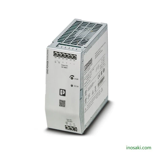
UNO2-PS/1AC/24DC/480W – 2910105 – Phoenix Contact Power Supply

USD $ 227.64

SKU: 2910105

Inosaki is one of the largest Phoenix Contact Distributors to provide terminal block, interface module, power supply and relay. And our best offer for terminal block types are Feed-through, Fuse Modular, Spring Cage, Double Level, and Multi-level, hence the series model references to  PT Series, ST Series, TB Series, UT Series, UK Series. In additional for power supply are QUINT Power, STEP Power, Trio Power, and UNO Power. Please email us for catalog: sales@inosaki.com

Dimensions

Width 59 mm
Height 130 mm
Depth 129 mm
125 mm (Device depth (DIN rail mounting))
Installation distance right/left (active, passive) 0 mm / 0 mm (POut ≥50% )
Installation distance top/bottom (active, passive) 30 mm / 30 mm (POut ≥50% )


Ambient conditions

Ambient temperature (operation) -25 °C … 70 °C (> 55 °C Derating: 2.5 %/K)
Ambient temperature (start-up type tested) -40 °C
Ambient temperature (storage/transport) -40 °C … 85 °C
Max. permissible relative humidity (operation) ≤ 95 % (at 25 °C, non-condensing)
Maximum altitude ≤ 3000 m (> 2000 m, Derating: 10 %/1000 m)
Degree of pollution 2
Climatic class 3K3 (in acc. with EN 60721)

Input data

Nominal input voltage range 100 V AC … 240 V AC
Input voltage range 100 V AC … 240 V AC -15 % … +10 %
Derating < 90 V AC (1 %/V)
Frequency range (fN) 50 Hz … 60 Hz 10 %
Typical national grid voltage 120 V AC
230 V AC
Voltage type of supply voltage AC
Current consumption 5.4 A (100 V AC)
4.4 A (120 V AC)
2.3 A (230 V AC)
2.2 A (240 V AC)
Discharge current to PE < 3.5 mA
Mains buffering time typ. 17 ms (120 V AC)
typ. 18 ms (230 V AC)
Switch-on time typ. 1 s
Inrush current typ. 15 A (at 25 °C)
Inrush current integral (I2t) < 1 A2s
Type of protection Transient protection
Protective circuit/component Varistor, gas-filled surge arrester
Device mains fuse 8 A internal (device protection), fast-blow
Recommended breaker for input protection 10 A … 16 A (Characteristic B, C, D, K or comparable)

Output data

Nominal output voltage 24 V DC
Setting range of the output voltage (USet) 24 V DC … 28 V DC (> 24 V DC, constant capacity restricted)
Nominal output current (IN) 20 A
Control deviation < 1 % (change in load, static 10 % … 90 %)
< 3 % (change in load, dynamic 10 % … 90 %)
< 0.1 % (change in input voltage ±10 %)
Short-circuit-proof yes
No-load proof yes
Residual ripple typ. 70 mVPP (with nominal values)
Connection in parallel yes, for redundancy
Connection in series yes, for increased output voltage
Feedback voltage resistance ≤ 35 V DC
Protection against overvoltage at the output (OVP) ≤ 35 V DC
Rise time < 1 s (UOut = 10 % … 90 %)
Derating 55 °C … 70 °C
Crest factor typ. 1,667 (120 V AC)
typ. 1,75 (230 V AC)
Minimum no-load power dissipation < 2.9 W (120 V AC)
Maximum power dissipation in no-load condition < 3 W (230 V AC)
Minimum nominal load power dissipation < 37 W (120 V AC)
Power loss nominal load max. < 28 W (230 V AC)

General

Article Number 2910105
Net weight 1 kg
Environmental protection directive RoHS Directive 2011/65/EU
WEEE
Reach
Efficiency typ. 93 % (120 V AC)
typ. 94.6 % (230 V AC)
MTBF (IEC 61709, SN 29500) > 900000 h (25 °C)
> 530000 h (40 °C)
> 280000 h (55 °C)
Insulation voltage input/output 4 kV AC (type test)
3 kV AC (routine test)
Insulation voltage input / PE 3.5 kV AC (type test)
2.4 kV AC (routine test)
Degree of protection IP20
Protection class I
Housing material Aluminum (AlMg3) / sheet steel, zinc-plated
Foot latch material Sheet steel, zinc-plated
Mounting position horizontal DIN rail NS 35, EN 60715
Assembly instructions alignable: 0 mm horizontally, 30 mm vertically

Input connection data

Connection method Screw connection
Stripping length 8 mm
Conductor cross section solid 0.2 mm² … 6 mm²
Conductor cross section flexible 0.2 mm² … 4 mm²
Flexible conductor cross section (ferrule with plastic sleeve) 0.25 mm² … 4 mm²
Flexible conductor cross section flexible (ferrule, w/o plastic sleeve) 0.25 mm² … 4 mm²
Conductor cross section AWG 24 … 10 (Cu)
Torque 0.5 Nm … 0.6 Nm

Output connection data

Connection method Screw connection
Stripping length 8 mm
Conductor cross section solid 0.2 mm² … 6 mm²
Conductor cross section flexible 0.2 mm² … 4 mm²
Flexible conductor cross section (ferrule with plastic sleeve) 0.25 mm² … 4 mm²
Flexible conductor cross section flexible (ferrule, w/o plastic sleeve) 0.25 mm² … 4 mm²
Conductor cross section AWG 24 … 10 (Cu)
Torque 0.5 Nm … 0.6 Nm

Signal connection data

Connection method Screw connection
Stripping length 8 mm
Conductor cross section solid 0.2 mm² … 6 mm²
Conductor cross section flexible 0.2 mm² … 4 mm²
Flexible conductor cross section (ferrule with plastic sleeve) 0.25 mm² … 4 mm²
Flexible conductor cross section flexible (ferrule, w/o plastic sleeve) 0.25 mm² … 4 mm²
Conductor cross section AWG 24 … 10 (Cu)
Torque 0.5 Nm … 0.6 Nm

LED signaling

Types of signaling LED DC OK – signal state operation (UN = 24 V DC, IOut = IN)

Signal contacts – signal output relay 13/14 (configurable)

Maximum contact load 30 V AC/DC
100 mA
Connection level 3.x
Connection labeling 3.1 (13), 3.2 (14)
Function Operating state forwarding
Switch contact OptoMOS
Switching voltage max. 30 V AC
max. 60 V DC
Current carrying capacity max. 50 mA
State condition UOUT > 0,9 x UN (Contact closed)
UOUT < 0,9 x UN (Contact open)

Standards

EMC requirements for noise immunity EN 61000-6-2
Standard designation Safety of power supply units up to 1100 V (insulation distances)
Standards/regulations DIN EN 61558-2-16
Standard designation Electrical safety
Standards/regulations IEC 61010-2-201 (SELV)
Standard designation Equipping high voltage installations with electronic equipment
Standards/regulations EN 50178/VDE 0160 (PELV)
Standard designation Safety for equipment for measurement, control, and laboratory use
Standards/regulations IEC 61010-1
Standard designation Protective extra-low voltage
Standards/regulations IEC 61010-1 (SELV)
IEC 61010-2-201 (PELV)
Standard designation Safe isolation
Standards/regulations IEC 61558-2-16
IEC 61010-2-201
Standard designation Limitation of harmonic line currents
Standards/regulations EN 61000-3-2
Standard designation Requirement of the semiconductor industry with regard to mains voltage dips
Standards/regulations SEMI F47 – 0706 (185 V AC)
Overvoltage category EN 61010-1 II (≤ 3000 m)
Overvoltage category EN 62477-1 III (≤3000 m)

Conformance/approvals

Designation UL
Identification UL/C-UL Listed UL 61010-1
Designation UL
Identification UL/C-UL Listed UL 61010-2-201
Designation UL
Identification UL/C-UL Listed ANSI/UL 121201 Class I, Division 2, Groups A, B, C, D (Hazardous Location)
Designation SIQ
Identification CB scheme (IEC 61010-1, IEC 61010-2-201)

EMC data

Electromagnetic compatibility Conformance with EMC Directive 2014/30/EU
Low Voltage Directive Conformance with Low Voltage Directive 2014/35/EC
Conducted noise emission EN 55016
EN 61000-6-3 (Class B)
Noise emission EN 55016
EN 61000-6-3 (Class B)
Harmonic currents EN 61000-3-2
EN 61000-3-2 (Class A)
Electrostatic discharge EN 61000-4-2
Contact discharge 6 kV (Test Level 3)
Discharge in air 8 kV (Test Level 3)
Electromagnetic HF field EN 61000-4-3
Frequency range 80 MHz … 1 GHz
Test field strength 10 V/m (Test Level 3)
Frequency range 1 GHz … 6 GHz
Test field strength 10 V/m (Test Level 3)
Comments Criterion A
Fast transients (burst) EN 61000-4-4
Input 4 kV (Test Level 4 – asymmetrical)
Output 2 kV (Test Level 3 – asymmetrical)
Comments Criterion A
Surge voltage load (surge) EN 61000-4-5
Input 2 kV (Test Level 3 – symmetrical)
4 kV (Test Level 4 – asymmetrical)
Output 1 kV (Test Level 2 – symmetrical)
2 kV (Test Level 3 – asymmetrical)
Comments Criterion A
Conducted interference EN 61000-4-6
Frequency range 0.15 MHz … 80 MHz
Voltage 10 V (Test Level 3)
Comments Criterion A
Voltage dips EN 61000-4-11
Voltage 230 V AC
Frequency 50 Hz
Voltage dip 70 %
Number of periods 25 / 30 periods
Comments Criterion A
Voltage dip 40 %
Number of periods 12 periods
Additional text Test Level 2
Comments Criterion A
Voltage dip 0 %
Number of periods 1 period
Additional text Test Level 2
Comments Criterion B
Criterion A Normal operating behavior within the specified limits.
Criterion B Temporary impairment to operational behavior that is corrected by the device itself.

Environmental Product Compliance

REACh SVHC Lead 7439-92-1
China RoHS Environmentally Friendly Use Period = 25;
For details about hazardous substances go to tab “Downloads”, Category “Manufacturer’s declaration”