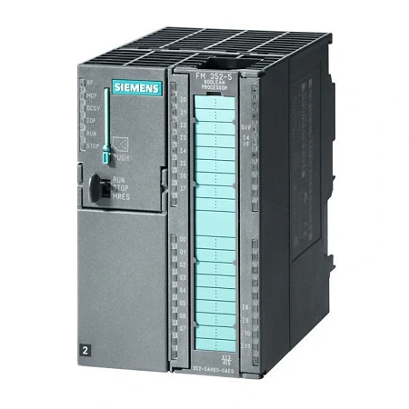
SIMATIC S7-300 – FM 352-5 High-Speed Boolean Processor – Siemens Function Modules
$ 959.90
SKU: 6ES7352-5AH01-0AE0
The FM 352-5 High-speed Boolean processor offers extremely fast binary functions and some of the quickest switching procedures ever possible.
Siemens Function Modules SIMATIC S7-300 Product Specifications:
| Article number | 6ES7352-5AH01-0AE0 |
| FM 352-5, Boolean Processor 12DE/8DA | |
| Supply voltage | |
| Load voltage L+ | |
| ● Rated value (DC) | 24 V |
| ● permissible range, lower limit (DC) | 20.4 V |
| ● permissible range, upper limit (DC) | 28.8 V |
| ● Reverse polarity protection | Yes |
| Input current | |
| from load voltage1L+, max. | 150 mA; typ. 60 mA |
| from load voltage 2L+ (without load), max. | 200 mA; typ. 60 mA, DI/DO supply |
| from load voltage 3L+ (with encoder), max. | 600 mA; typ. 80 mA plus encoder supply |
| from load voltage 3L+ (without load), max. | 200 mA; typ. 80 mA |
| from backplane bus 5 V DC, typ. | 135 mA |
| Encoder supply | |
| 5 V encoder supply | |
| ● 5 V | Yes |
| ● Short-circuit protection | Yes; Electronic overload protection; no protection on applying a normal or counter voltage. |
| ● Output current, max. | 250 mA |
| 24 V encoder supply | |
| ● 24 V | Yes |
| ● Short-circuit protection | Yes; Overvoltage and overheating protection if overloaded; diagnostics if output reaches temperature limit; no protection on applying a normal or counter voltage |
| ● Output current, max. | 400 mA |
| Power loss | |
| Power loss, typ. | 6.5 W |
| Memory | |
| Type of memory | RAM |
| Memory size | 128 kbyte; required for operation, MMC |
| Digital inputs | |
| Number of digital inputs | 8; Standard and up to 12 with 24 V DC encoder inputs as digital inputs |
| Input voltage | |
| ● Rated value (DC) | 24 V |
| ● for signal “0” | -30 to +5 V |
| ● for signal “1” | +11 to +30V |
| Input current | |
| ● for signal “0”, max. (permissible quiescent current) | 1.5 mA |
| ● for signal “1”, typ. | 3.8 mA |
| Input delay (for rated value of input voltage) | |
| ● Input frequency (with a time delay of 0.1 ms), max. | 200 kHz |
| ● programmable digital filter delay | None, 5 µs, 10 µs, 15 µs, 20 µs, 50 µs, 1.6 ms |
| ● Minimum pulse width for program reactions | 1 µs, 5 µs, 10 µs, 15 µs, 20 µs, 50 µs, 1,6 ms |
| for standard inputs | |
| — at “0” to “1”, max. | 3 µs; typ. 1.5 µs |
| Cable length | |
| ● shielded, max. | 600 m |
| ● unshielded, max. | 100 m; Shielded cable recommended if filtering delay is set to less than 1.6 ms |
| Digital outputs | |
| Number of digital outputs | 8 |
| Current-sinking | Yes |
| Current-sourcing | No |
| Short-circuit protection | Yes; Overvoltage protection, thermal protection |
| ● Response threshold, typ. | 1.7 to 3.5 A |
| Limitation of inductive shutdown voltage to | 2M -45 V typ., (-40 V to -55 V); comment: no protection against inductive kickback >55 mJ |
| Controlling a digital input | No |
| Switching capacity of the outputs | |
| ● on lamp load, max. | 5 W |
| Output voltage | |
| ● Rated value (DC) | 24 V |
| ● for signal “0”, max. | 28.8 V |
| ● for signal “1”, max. | 0.5 V |
| Output current | |
| ● for signal “1” rated value | 0.5 A; At 60 °C |
| ● for signal “1” permissible range for 0 to 60 °C, min. | 5 mA |
| ● for signal “1” permissible range for 0 to 60 °C, max. | 600 mA |
| ● for signal “0” residual current, max. | 1 mA |
| Output delay with resistive load | |
| ● “0” to “1”, max. | 1 µs; 0.6 µs 50 mA / 1.0 µs 0.5 A |
| ● “1” to “0”, max. | 1.5 µs; 1.7 µs 50 mA / 1.5 µs 0.5 A |
| Parallel switching of two outputs | |
| ● for uprating | Yes; 2 |
| Switching frequency | |
| ● with resistive load, max. | 100 kHz; 20 kHz at 0.5 A; 100 kHz at 0.25 A |
| ● with inductive load, max. | 2 Hz; 2 Hz at 0.5 A with external commutator diodes; 0.5 Hz at 0.5 A without external commutator diodes |
| ● on lamp load, max. | 10 Hz |
| Cable length | |
| ● shielded, max. | 600 m |
| ● unshielded, max. | 100 m |
| Encoder | |
| Connectable encoders | |
| ● Incremental encoder (symmetrical) | Yes |
| ● Incremental encoder (asymmetrical) | Yes |
| ● Absolute encoder (SSI) | Yes |
| ● 2-wire sensor | Yes |
| — permissible quiescent current (2-wire sensor), max. | 1.5 mA |
| Encoder signals, incremental encoder (symmetrical) | |
| ● Trace mark signals | A, notA, B, notB |
| ● Zero mark signal | N, notN |
| ● Input voltage | 5 V difference signal (phys. RS 422) |
| ● Input frequency, max. | 500 kHz |
| ● Cable length, shielded, max. | 100 m; 100 m with 24 V supply and 500 kHz; 32 m with 5 V supply and 500 kHz |
| Encoder signals, incremental encoder (asymmetrical) | |
| ● Trace mark signals | A, B |
| ● Zero mark signal | N |
| ● Input voltage | 24 V |
| ● Input frequency, max. | 200 kHz |
| ● Cable length, shielded, max. | 50 m; Cable length, HTL incremental encoder, Siemens, type 6FX2001-4: 50 kHz, 25 m shielded, max., 25 kHz, 50 m shielded, max. |
| Encoder signals, absolute encoder (SSI) | |
| ● Data signal | DATA, notDATA |
| ● Clock signal | CK, notCK |
| ● Telegram length, parameterizable | 13 or 25 bit |
| ● Clock frequency, max. | 1 MHz; 125 kHz, 250 kHz, 500 kHz or 1 MHz |
| ● Cable length, shielded, max. | 320 m; At 125 kHz |
| ● Monoflop time | settable: 16/32/48/64 µs |
| ● Listening mode | Yes; one or two stations |
| ● Multiturn | Yes; 25 bit message frame |
| Encoder signal evaluation | |
| ● Counting direction, forward | Yes |
| ● Counting direction, backward | Yes |
| Response times | |
| Input- to output response time | 5 V input to 24 V output, 0 filter: 1 to 4 µs (typ.); 24 V input to 24 V output, 0 filter: 2 to 6 µs (typ.) |
| Interfaces | |
| Point-to-point connection | |
| ● Updating times | PLC interface: 1.7 ms |
| Interrupts/diagnostics/status information | |
| Alarms | |
| ● Diagnostic alarm | Yes; 1L, 2L, 3L missing; MMC error; output overload (8); encoder supply overload; differential wire break; parameterization errror; SSI message frame overflow |
| ● Hardware interrupt | Yes; 8 available; for generation by user program |
| Diagnoses | |
| ● Wire-break in signal transmitter cable | Yes |
| ● Overflow/underflow | Yes |
| ● missing load voltage | Yes |
| Diagnostics indication LED | |
| ● RUN/STOP LED | Yes |
| ● Module supply 5 V DC (green) | Yes |
| ● I/O status IOF (red) | Yes |
| ● Micro Memory Card error MCF (red) | Yes |
| ● Group error SF (red) | Yes |
| ● Status indicator digital input (green) | Yes; I 0 to I 11 |
| ● Status indicator digital output (green) | Yes; Q 0 to Q 7 |
| ● Overload encoder supply voltage 24 V F (red) | Yes |
| ● Overload encoder supply voltage 5 V F (red) | Yes |
| Counter | |
| Counting range, description | Counting range (16-bit counters): -32 768 to 32 767 (user-specific within this range); counting range (32-bit counters): -2 147 483 648 to 2 147 483 647 (user-specific within this range) |
| Counting range, lower limit | -2 147 483 648 |
| Counting range, upper limit | 2 147 483 647 |
| Counting mode | |
| ● Counting mode, individual | Yes |
| ● Counting mode, continuous | Yes |
| ● Counting mode, periodic | Yes |
| Potential separation | |
| between 1L and 2L and 3L | Yes |
| Potential separation digital inputs | |
| ● Potential separation digital inputs | Yes; Yes CPU, I/O and sensor units are isolated |
| Ambient conditions | |
| Ambient temperature during operation | |
| ● min. | 0 °C |
| ● max. | 60 °C |
| Ambient temperature during storage/transportation | |
| ● min. | -40 °C |
| ● max. | 70 °C |
| configuration / header | |
| configuration / programming / header | |
| ● Program cycle time (scan) | 1 µs |
| connection method / header | |
| required front connector | 1x 40-pin |
| Dimensions | |
| Width | 80 mm |
| Height | 125 mm |
| Depth | 120 mm |
| Weights | |
| Weight, approx. | 434 g; Module weight: approx. 434 g (with 1L connection and without I/O connection or MMC); shipping weight: approx. 500 g (with bus and 1L connection and without I/O connection or MMC) |
| Weight | 0.537 kg |
|---|---|
| Dimensions | 12.9 × 15.4 × 8.9 cm |
Related products
-
 Select options This product has multiple variants. The options may be chosen on the product page Details
 -
 Select options This product has multiple variants. The options may be chosen on the product page Details
 -
 Select options This product has multiple variants. The options may be chosen on the product page Details
 -
 Select options This product has multiple variants. The options may be chosen on the product page Details
 -
 Select options This product has multiple variants. The options may be chosen on the product page Details
 -
 Select options This product has multiple variants. The options may be chosen on the product page Details

