USD 304.72 – USD 498.16Price range: USD 304.72 through USD 498.16
The distributed I/O system ET 200SP offers a comprehensive portfolio of analog inputs, modules with standard functionality (ST) as well as enhanced functions (HF High Feature / HS High Speed)
Especially for price sensitive applications there are modules available that offer basic functionality (BA).
Option of connecting current, voltage and resistance sensors, as well as thermocouples.
The most common modules are also available in packs of ten, which avoids packaging material and speeds up unpacking.
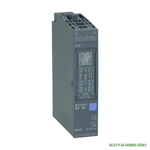
The High Speed Analog Input Module AI 2xU/I 2-/4-wire HS offers oversampling as enhanced functioanality.
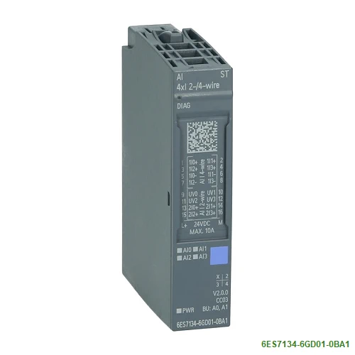
| Article number | 6ES7134-6GD01-0BA1 | 6ES7134-6TD00-0CA1 | 6ES7134-6HB00-0CA1 | 6ES7134-6HB00-0DA1 |
| ET 200SP, AI 4XI 2-/4-Wire ST, PU 1 | ET 200SP, AI 4XI 2-WIRE 4…20MA HART | ET 200SP AI 2 X U/I 2-, 4-Wire HF | ET 200SP AI 2 X U/I 2-, 4-Wire HS | |
| General information | ||||
| Product type designation | AI 4xI 2-/4-wire ST | AI 4xI 2-wire HART | AI 2xU/I 2-/4-wire HF | AI 2xU/I 2-/4-wire HS |
| HW functional status | From FS02 | From FS06 | From FS07 | |
| Firmware version | V1.0 | |||
| ● FW update possible | Yes | Yes | Yes | Yes |
| usable BaseUnits | BU type A0, A1 | BU type A0, A1 | BU type A0, A1 | BU type A0, A1 |
| Color code for module-specific color identification plate | CC03 | CC03 | CC03 | CC00 |
| Product function | ||||
| ● I&M data | Yes; I&M0 to I&M3 | Yes; I&M0 to I&M3 | Yes; I&M0 to I&M3 | Yes; I&M0 to I&M3 |
| ● Isochronous mode | No | No | Yes | Yes |
| ● Measuring range scalable | No | No | No | No |
| ● Scalable measured values | No | |||
| ● Adjustment of measuring range | No | |||
| Engineering with | ||||
| ● STEP 7 TIA Portal configurable/integrated from version | V14 / – | V13 SP1 | V13 | V13 SP1 |
| ● STEP 7 configurable/integrated from version | V5.6 and higher | V5.5 SP4 and higher | V5.5 / – | V5.5 SP3 / – |
| ● PCS 7 configurable/integrated from version | V8.1 SP1 | V8.1 SP1 | V8.1 SP1 | |
| ● PROFIBUS from GSD version/GSD revision | One GSD file each, Revision 3 and 5 and higher | GSD Revision 5 | One GSD file each, Revision 3 and 5 and higher | One GSD file each, Revision 3 and 5 and higher |
| ● PROFINET from GSD version/GSD revision | GSDML V2.3 | GSDML V2.3 | GSDML V2.3 | GSDML V2.3 |
| Operating mode | ||||
| ● Oversampling | No | No | No | Yes; 2 channels per module |
| ● MSI | No | No | Yes | No |
| CiR – Configuration in RUN | ||||
| Reparameterization possible in RUN | Yes | Yes | Yes | Yes |
| Calibration possible in RUN | No | No | Yes | No |
| Supply voltage | ||||
| Rated value (DC) | 24 V | 24 V | 24 V | 24 V |
| permissible range, lower limit (DC) | 19.2 V | 19.2 V | 19.2 V | 19.2 V |
| permissible range, upper limit (DC) | 28.8 V | 28.8 V | 28.8 V | 28.8 V |
| Reverse polarity protection | Yes | Yes | Yes | Yes |
| Input current | ||||
| Current consumption (rated value) | 39 mA; without sensor supply | 39 mA; without sensor supply | ||
| Current consumption, max. | 37 mA; without sensor supply | 25 mA; without sensor supply | ||
| Encoder supply | ||||
| 24 V encoder supply | ||||
| ● 24 V | Yes | Yes | Yes | Yes; For current measurement |
| ● Short-circuit protection | Yes | Yes | Yes | Yes |
| ● Output current, max. | 20 mA; max. 50 mA per channel for a duration < 10 s | 20 mA; max. 50 mA per channel for a duration < 10 s | 20 mA; max. 50 mA per channel for a duration < 10 s (two-wire) | 20 mA; max. 50 mA per channel for a duration < 10 s |
| Additional 24 V encoder supply | ||||
| ● Short-circuit protection | Yes; channel by channel | |||
| ● Output current, max. | 100 mA; max. 150 mA for a duration of < 10 s (four-wire) | |||
| Power loss | ||||
| Power loss, typ. | 0.85 W; Without encoder supply voltage | 0.65 W; without sensor supply | 0.95 W; without sensor supply | 0.95 W; without sensor supply |
| Address area | ||||
| Address space per module | ||||
| ● Address space per module, max. | 8 byte; + 1 byte for QI information | 8 byte; + 1 byte for QI information | 4 byte; + 4 byte for scaling of measured values, + 1 byte for QI information | 4 byte; + 1 byte for QI information (32 bytes in the oversampling operating mode) |
| ● Address space per module with HART, max. | 28 byte; + 1 byte for QI information | |||
| Hardware configuration | ||||
| Automatic encoding | Yes | Yes | Yes | Yes |
| ● Mechanical coding element | Yes | Yes | Yes | Yes |
| ● Type of mechanical coding element | Type A | Type A | Type A | Type A |
| Selection of BaseUnit for connection variants | ||||
| ● 2-wire connection | BU type A0, A1 | BU type A0, A1 | BU type A0, A1 | |
| ● 4-wire connection | BU type A0, A1 | BU type A0, A1 | BU type A0, A1 | |
| Analog inputs | ||||
| Number of analog inputs | 4; Differential inputs | 4; Differential inputs | 2; Differential inputs | 2; Differential inputs |
| ● For current measurement | 4 | 2 | 2 | |
| ● For voltage measurement | 2 | 2 | ||
| permissible input voltage for voltage input (destruction limit), max. | 30 V | 30 V | ||
| permissible input current for current input (destruction limit), max. | 50 mA | 50 mA | 50 mA | 50 mA |
| Cycle time (all channels), min. | Sum of the basic conversion times and additional processing times (depending on the parameterization of the active channels) | 125 µs | ||
| Analog input with oversampling | No | Yes | ||
| ● Values per cycle, max. | 16 | |||
| ● Resolution, min. | 50 µs | |||
| Standardization of measured values | Yes | |||
| Input ranges (rated values), voltages | ||||
| ● 0 to +10 V | Yes; 15 bit | Yes; 15 bit | ||
| — Input resistance (0 to 10 V) | 75 kΩ | 75 kΩ | ||
| ● 1 V to 5 V | Yes; 15 bit | Yes; 13 bit | ||
| — Input resistance (1 V to 5 V) | 75 kΩ | 75 kΩ | ||
| ● -10 V to +10 V | Yes; 16 bit incl. sign | Yes; 16 bit incl. sign | ||
| — Input resistance (-10 V to +10 V) | 75 kΩ | 75 kΩ | ||
| ● -5 V to +5 V | Yes; 16 bit incl. sign | Yes; 15 bit incl. sign | ||
| — Input resistance (-5 V to +5 V) | 75 kΩ | 75 kΩ | ||
| Input ranges (rated values), currents | ||||
| ● 0 to 20 mA | Yes; 16 bit incl. sign | No | Yes; 15 bit | Yes; 15 bit |
| — Input resistance (0 to 20 mA) | 100 Ω; + approx. 0.7 V diode forward voltage in 2-wire operation | 130 Ω | 130 Ω | |
| ● -20 mA to +20 mA | Yes | No | Yes; 16 bit incl. sign | Yes; 16 bit incl. sign |
| — Input resistance (-20 mA to +20 mA) | 100 Ω | 130 Ω | 130 Ω | |
| ● 4 mA to 20 mA | Yes; 15 bit | Yes; 15 bit + sign | Yes; 15 bit | Yes; 14 bit |
| — Input resistance (4 mA to 20 mA) | 100 Ω; + approx. 0.7 V diode forward voltage in 2-wire operation | 280 Ω; + approx. 0.35 V diode forward voltage | 130 Ω | 130 Ω |
| Cable length | ||||
| ● shielded, max. | 1 000 m | 800 m | 1 000 m; 200 m for voltage measurement | 1 000 m; 200 m for voltage measurement |
| Analog value generation for the inputs | ||||
| Measurement principle | integrating (Sigma-Delta) | integrating (Sigma-Delta) | Sigma Delta | Actual value encryption (successive approximation) |
| Integration and conversion time/resolution per channel | ||||
| ● Resolution with overrange (bit including sign), max. | 16 bit | 16 bit | 16 bit | 16 bit |
| ● Integration time, parameterizable | Yes | Yes; channel by channel | Yes | |
| ● Integration time (ms) | 67.5 / 22.5 / 18.75 / 10 / 5 / 2.5 / 1.25 / 0.625 ms | |||
| ● Basic conversion time, including integration time (ms) | 68.03 / 22.83 / 19.03 / 10.28 / 5.23 / 2.68 / 1.43 / 0.730 ms | |||
| ● Interference voltage suppression for interference frequency f1 in Hz | 16.6 / 50 / 60 Hz | 10 / 50 / 60 Hz | 16.6 / 50 / 60 / 300 / 600 / 1 200 / 2 400 / 4 800 | No |
| ● Conversion time (per channel) | 180 / 60 / 50 ms | 68.2 / 23 / 19.2 / 10.45 / 5.40 / 2.85 / 1.6 / 0.9 ms | 10 µs | |
| ● Basic execution time of the module (all channels released) | 1 ms | |||
| Smoothing of measured values | ||||
| ● Number of smoothing levels | 4; None; 4/8/16 times | 4; None; 4/8/16 times | 6; none; 2-/4-/8-/16-/32-fold | 7; none; 2-/4-/8-/16-/32-/64-fold |
| ● parameterizable | Yes | Yes | Yes | Yes |
| Encoder | ||||
| Connection of signal encoders | ||||
| ● for voltage measurement | No | No | Yes | Yes |
| ● for current measurement as 2-wire transducer | Yes | Yes | Yes | Yes |
| — Burden of 2-wire transmitter, max. | 650 Ω | 650 Ω | 650 Ω | |
| ● for current measurement as 4-wire transducer | Yes | Yes | Yes | |
| Errors/accuracies | ||||
| Linearity error (relative to input range), (+/-) | 0.01 % | 0.01 % | 0.01 % | 0.03 % |
| Temperature error (relative to input range), (+/-) | 0.005 %/K | 0.005 %/K | 0.003 %/K | 0.01 %/K |
| Crosstalk between the inputs, min. | 50 dB; Applies to up to ±5 V overvoltage in other channels | 60 dB | -50 dB | -50 dB |
| Repeat accuracy in steady state at 25 °C (relative to input range), (+/-) | 0.05 % | 0.05 % | 0.01 % | 0.1 % |
| Operational error limit in overall temperature range | ||||
| ● Voltage, relative to input range, (+/-) | 0.1 % | 0.3 % | ||
| ● Current, relative to input range, (+/-) | 0.5 % | 0.5 % | 0.1 % | 0.3 % |
| Basic error limit (operational limit at 25 °C) | ||||
| ● Voltage, relative to input range, (+/-) | 0.05 %; 0.1 % at SFU 4.8 kHz | 0.2 % | ||
| ● Current, relative to input range, (+/-) | 0.3 % | 0.3 % | 0.05 %; 0.1 % at SFU 4.8 kHz | 0.2 % |
| Interference voltage suppression for f = n x (f1 +/- 1 %), f1 = interference frequency | ||||
| ● Series mode interference (peak value of interference < rated value of input range), min. | 70 dB | 60 dB | ||
| ● Common mode voltage, max. | 10 V | 35 V | 35 V | |
| ● Common mode interference, min. | 90 dB | 90 dB | 90 dB | |
| Isochronous mode | ||||
| Filtering and processing time (TCI), min. | 800 µs | 80 µs | ||
| Bus cycle time (TDP), min. | 1 ms | 125 µs; Starting from firmware Version V2.0.1 | ||
| Jitter, max. | 5 µs | |||
| Interrupts/diagnostics/status information | ||||
| Diagnostics function | Yes | Yes | Yes | |
| Alarms | ||||
| ● Diagnostic alarm | Yes | Yes | Yes | Yes |
| ● Limit value alarm | No | Yes | Yes; two upper and two lower limit values in each case | Yes; two upper and two lower limit values in each case |
| Diagnoses | ||||
| ● Monitoring the supply voltage | Yes | Yes | Yes | |
| ● Wire-break | Yes; at 4 to 20 mA | Yes; channel by channel | Yes; Measuring range 4 to 20 mA only | Yes; channel-by-channel, at 4 to 20 mA only |
| ● Short-circuit | Yes; 2-wire mode: Short-circuit of the encoder supply to ground or of an input to the encoder supply | Yes; Channel-by-channel, short-circuit of the encoder supply to ground or of an input to the encoder supply | Yes; channel-by-channel, at 1 to 5 V or for short-circuit in encoder supply | Yes; channel-by-channel, at 1 to 5 V or for current measuring ranges short-circuit in encoder supply |
| ● Group error | Yes | Yes | Yes | Yes |
| ● Overflow/underflow | Yes | Yes; channel by channel | Yes | Yes |
| Diagnostics indication LED | ||||
| ● Monitoring of the supply voltage (PWR-LED) | Yes; green LED | Yes; green PWR LED | Yes; green PWR LED | Yes; green PWR LED |
| ● Channel status display | Yes; green LED | Yes; green LED | Yes; green LED | Yes; green LED |
| ● for channel diagnostics | No | Yes; red LED | Yes; red LED | Yes; red LED |
| ● for module diagnostics | Yes; green/red LED | Yes; green/red DIAG LED | Yes; green/red DIAG LED | Yes; green/red DIAG LED |
| Potential separation | ||||
| Potential separation channels | ||||
| ● between the channels | Yes; channel group-specific between 2-wire current input group and 4-wire voltage input group | No | Yes | Yes |
| ● between the channels and backplane bus | Yes | Yes | Yes | Yes |
| ● between the channels and the power supply of the electronics | Yes; only for 4-wire transducer | No | Yes | Yes |
| Permissible potential difference | ||||
| between the inputs (UCM) | 10 V DC | |||
| Isolation | ||||
| Isolation tested with | 707 V DC (type test) | 707 V DC (type test) | 707 V DC (type test) | 707 V DC (type test) |
| Ambient conditions | ||||
| Ambient temperature during operation | ||||
| ● horizontal installation, min. | -30 °C; < 0 °C as of FS02 | -30 °C | -30 °C; < 0 °C as of FS06 | -30 °C |
| ● horizontal installation, max. | 60 °C | 60 °C | 60 °C | 60 °C |
| ● vertical installation, min. | -30 °C; < 0 °C as of FS02 | -30 °C | -30 °C; < 0 °C as of FS06 | -30 °C |
| ● vertical installation, max. | 50 °C | 50 °C | 50 °C | 50 °C |
| Altitude during operation relating to sea level | ||||
| ● Installation altitude above sea level, max. | 5 000 m; Restrictions for installation altitudes > 2 000 m, see manual | 5 000 m; restrictions for installation altitudes > 2 000 m, see ET 200SP system manual | 5 000 m; Restrictions for installation altitudes > 2 000 m, see manual | 5 000 m; Restrictions for installation altitudes > 2 000 m, see manual |
| Dimensions | ||||
| Width | 15 mm | 15 mm | 15 mm | 15 mm |
| Height | 73 mm | 73 mm | 73 mm | 73 mm |
| Depth | 58 mm | 58 mm | 58 mm | 58 mm |
| Weights | ||||
| Weight, approx. | 31 g | 31 g | 32 g | 32 g |
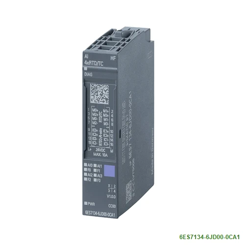
| Article number | 6ES7134-6JF00-0CA1 | 6ES7134-6JD00-0CA1 | 6ES7134-6JD00-0DA1 |
| ET 200SP, AI 8xRTD/TC 2-Wire HF | ET 200SP, AI 4xRTD/TC 2-/3-/4-Wire HF | ET 200SP, AI 4x TC HS | |
| General information | |||
| Product type designation | AI 8xRTD/TC 2-wire HF | AI 4xRTD/TC 2-/3-/4-wire HF | AI 4xTC HS |
| HW functional status | From FS05 | From FS02 | |
| Firmware version | V2.1 | V2.1 | |
| ● FW update possible | Yes | Yes | Yes |
| usable BaseUnits | BU type A0, A1 | BU type A0, A1 | BU type A0, A1 |
| Color code for module-specific color identification plate | CC00 | CC00 | CC00 |
| Product function | |||
| ● I&M data | Yes; I&M0 to I&M3 | Yes; I&M0 to I&M3 | Yes; I&M0 to I&M3 |
| ● Isochronous mode | No | No | No |
| ● Measuring range scalable | Yes | Yes | |
| ● Adjustment of measuring range | Yes | ||
| Engineering with | |||
| ● STEP 7 TIA Portal configurable/integrated from version | V16, V17 / V18 | V12 SP1 / V13 | V15 with HSP 265/integrated as of V15.1 |
| ● STEP 7 configurable/integrated from version | V5.5 SP3 / V5.5 SP4 | V5.5 SP3 / V5.5 SP4 | V5.5 SP3 or higher |
| ● PCS 7 configurable/integrated from version | V8.1 SP1 | V8.1 SP1 | |
| ● PROFIBUS from GSD version/GSD revision | One GSD file each, Revision 3 and 5 and higher | GSD Revision 5 | One GSD file each, Revision 3 and 5 and higher |
| ● PROFINET from GSD version/GSD revision | GSDML V2.35 | GSDML V2.3 | GSDML V2.3 |
| Operating mode | |||
| ● Oversampling | No | No | |
| ● MSI | No | Yes | |
| CiR – Configuration in RUN | |||
| Reparameterization possible in RUN | Yes | Yes | Yes |
| Calibration possible in RUN | Yes | Yes | Yes |
| Supply voltage | |||
| Rated value (DC) | 24 V | 24 V | 24 V |
| permissible range, lower limit (DC) | 19.2 V | 19.2 V | 19.2 V |
| permissible range, upper limit (DC) | 28.8 V | 28.8 V | 28.8 V |
| Reverse polarity protection | Yes | Yes | Yes |
| Input current | |||
| Current consumption (rated value) | 37 mA | ||
| Current consumption, max. | 35 mA | 50 mA | |
| Power loss | |||
| Power loss, typ. | 0.75 W | 0.75 W | 0.9 W |
| Address area | |||
| Address space per module | |||
| ● Address space per module, max. | 16 byte; + 1 byte for QI information | 8 byte; + 1 byte for QI information | 16 byte; + 1 byte for QI information |
| Hardware configuration | |||
| Automatic encoding | Yes | ||
| ● Mechanical coding element | Yes | Yes | |
| ● Type of mechanical coding element | Type A | Type A | Type A |
| Selection of BaseUnit for connection variants | |||
| ● 2-wire connection | BU type A0, A1 | BU type A0, A1 | |
| Analog inputs | |||
| Number of analog inputs | 8 | 4 | 4 |
| permissible input voltage for voltage input (destruction limit), max. | 30 V | 30 V | 30 V |
| Constant measurement current for resistance-type transmitter, typ. | 2 mA | 2 mA | |
| Cycle time (all channels), min. | Sum of the basic conversion times and additional processing times (depending on the parameterization of the active channels) | Sum of the basic conversion times and additional processing times (depending on the parameterization of the active channels); for line compensation in case of a three-wire connection, an additional cycle is necessary | 5 ms; Sum of the basic conversion times and additional processing times (depending on the parameterization of the active channels) |
| Technical unit for temperature measurement adjustable | Yes; °C/°F/K | Yes; °C/°F/K | Yes; °C/°F/K |
| Input ranges (rated values), voltages | |||
| ● -1 V to +1 V | Yes; 16 bit incl. sign | Yes; 16 bit incl. sign | Yes; 16 bit incl. sign |
| — Input resistance (-1 V to +1 V) | 1 MΩ | 1 MΩ | 1 MΩ |
| ● -250 mV to +250 mV | Yes; 16 bit incl. sign | Yes; 16 bit incl. sign | Yes; 16 bit incl. sign |
| — Input resistance (-250 mV to +250 mV) | 1 MΩ | 1 MΩ | 1 MΩ |
| ● -50 mV to +50 mV | Yes; 16 bit incl. sign | Yes; 16 bit incl. sign | Yes; 16 bit incl. sign |
| — Input resistance (-50 mV to +50 mV) | 1 MΩ | 1 MΩ | 1 MΩ |
| ● -80 mV to +80 mV | Yes; 16 bit incl. sign | Yes; 16 bit incl. sign | Yes; 16 bit incl. sign |
| — Input resistance (-80 mV to +80 mV) | 1 MΩ | 1 MΩ | 1 MΩ |
| Input ranges (rated values), thermocouples | |||
| ● Type B | Yes; 16 bit incl. sign | Yes; 16 bit incl. sign | Yes; 16 bit incl. sign |
| — Input resistance (Type B) | 1 MΩ | 1 MΩ | 1 MΩ |
| ● Type C | Yes; 16 bit incl. sign | Yes; 16 bit incl. sign | Yes; 16 bit incl. sign |
| — Input resistance (Type C) | 1 MΩ | 1 MΩ | 1 MΩ |
| ● Type E | Yes; 16 bit incl. sign | Yes; 16 bit incl. sign | Yes; 16 bit incl. sign |
| — Input resistance (Type E) | 1 MΩ | 1 MΩ | 1 MΩ |
| ● Type J | Yes; 16 bit incl. sign | Yes; 16 bit incl. sign | Yes; 16 bit incl. sign |
| — Input resistance (type J) | 1 MΩ | 1 MΩ | 1 MΩ |
| ● Type K | Yes; 16 bit incl. sign | Yes; 16 bit incl. sign | Yes; 16 bit incl. sign |
| — Input resistance (Type K) | 1 MΩ | 1 MΩ | 1 MΩ |
| ● Type L | Yes; 16 bit incl. sign | Yes; 16 bit incl. sign | Yes; 16 bit incl. sign |
| — Input resistance (Type L) | 1 MΩ | 1 MΩ | 1 MΩ |
| ● Type N | Yes; 16 bit incl. sign | Yes; 16 bit incl. sign | Yes; 16 bit incl. sign |
| — Input resistance (Type N) | 1 MΩ | 1 MΩ | 1 MΩ |
| ● Type R | Yes; 16 bit incl. sign | Yes; 16 bit incl. sign | Yes; 16 bit incl. sign |
| — Input resistance (Type R) | 1 MΩ | 1 MΩ | 1 MΩ |
| ● Type S | Yes; 16 bit incl. sign | Yes; 16 bit incl. sign | Yes; 16 bit incl. sign |
| — Input resistance (Type S) | 1 MΩ | 1 MΩ | 1 MΩ |
| ● Type T | Yes; 16 bit incl. sign | Yes; 16 bit incl. sign | Yes; 16 bit incl. sign |
| — Input resistance (Type T) | 1 MΩ | 1 MΩ | 1 MΩ |
| ● Type U | Yes; 16 bit incl. sign | Yes; 16 bit incl. sign | Yes; 16 bit incl. sign |
| — Input resistance (Type U) | 1 MΩ | 1 MΩ | 1 MΩ |
| ● Type TXK/TXK(L) to GOST | Yes; 16 bit incl. sign | Yes; 16 bit incl. sign | Yes; 16 bit incl. sign |
| — Input resistance (Type TXK/TXK(L) to GOST) | 1 MΩ | 1 MΩ | 1 MΩ |
| Input ranges (rated values), resistance thermometer | |||
| ● Cu 10 | Yes; 16 bit incl. sign | ||
| — Input resistance (Cu 10) | 1 MΩ | ||
| ● Ni 100 | Yes; 16 bit incl. sign | Yes; 16 bit incl. sign | |
| — Input resistance (Ni 100) | 1 MΩ | 1 MΩ | |
| ● Ni 1000 | Yes; 16 bit incl. sign | Yes; 16 bit incl. sign | |
| — Input resistance (Ni 1000) | 1 MΩ | 1 MΩ | |
| ● LG-Ni 1000 | Yes; 16 bit incl. sign | Yes; 16 bit incl. sign | |
| — Input resistance (LG-Ni 1000) | 1 MΩ | 1 MΩ | |
| ● Ni 120 | Yes; 16 bit incl. sign | Yes; 16 bit incl. sign | |
| — Input resistance (Ni 120) | 1 MΩ | 1 MΩ | |
| ● Ni 200 | Yes; 16 bit incl. sign | Yes; 16 bit incl. sign | |
| — Input resistance (Ni 200) | 1 MΩ | 1 MΩ | |
| ● Ni 500 | Yes; 16 bit incl. sign | Yes; 16 bit incl. sign | |
| — Input resistance (Ni 500) | 1 MΩ | 1 MΩ | |
| ● Pt 100 | Yes; 16 bit incl. sign | Yes; 16 bit incl. sign | |
| — Input resistance (Pt 100) | 1 MΩ | 1 MΩ | |
| ● Pt 1000 | Yes; 16 bit incl. sign | Yes; 16 bit incl. sign | |
| — Input resistance (Pt 1000) | 1 MΩ | 1 MΩ | |
| ● Pt 200 | Yes; 16 bit incl. sign | Yes; 16 bit incl. sign | |
| — Input resistance (Pt 200) | 1 MΩ | 1 MΩ | |
| ● Pt 500 | Yes; 16 bit incl. sign | Yes; 16 bit incl. sign | |
| — Input resistance (Pt 500) | 1 MΩ | 1 MΩ | |
| Input ranges (rated values), resistors | |||
| ● 0 to 150 ohms | Yes; 15 bit | Yes; 15 bit | |
| — Input resistance (0 to 150 ohms) | 1 MΩ | 1 MΩ | |
| ● 0 to 300 ohms | Yes; 15 bit | Yes; 15 bit | |
| — Input resistance (0 to 300 ohms) | 1 MΩ | 1 MΩ | |
| ● 0 to 600 ohms | Yes; 15 bit | Yes; 15 bit | |
| — Input resistance (0 to 600 ohms) | 1 MΩ | 1 MΩ | |
| ● 0 to 3000 ohms | Yes; 15 bit | Yes; 15 bit | |
| — Input resistance (0 to 3000 ohms) | 1 MΩ | 1 MΩ | |
| ● 0 to 6000 ohms | Yes; 15 bit | Yes; 15 bit | |
| — Input resistance (0 to 6000 ohms) | 1 MΩ | 1 MΩ | |
| ● PTC | Yes; 15 bit | Yes; 15 bit | |
| — Input resistance (PTC) | 1 MΩ | 1 MΩ | |
| Thermocouple (TC) | |||
| Temperature compensation | |||
| — parameterizable | Yes | Yes | Yes |
| — Reference channel of the module | Yes | Yes | No |
| — internal comparison point | Yes; with BaseUnit type A1 | Yes; with BaseUnit type A1 | Yes; with BaseUnit type A1 |
| — Reference channel of the group | Yes | Yes | |
| — Number of reference channel groups | 4; Group 0 to 3 | 4; Group 0 to 3 | 4; Group 0 to 3 |
| — fixed reference temperature | Yes | Yes | |
| Cable length | |||
| ● shielded, max. | 200 m; 50 m with thermocouples | 200 m; 50 m with thermocouples | 200 m; 100 m for thermocouples |
| Analog value generation for the inputs | |||
| Measurement principle | integrating (Sigma-Delta) | integrating (Sigma-Delta) | integrating (Sigma-Delta) |
| Integration and conversion time/resolution per channel | |||
| ● Resolution with overrange (bit including sign), max. | 16 bit | 16 bit | 16 bit |
| ● Integration time, parameterizable | Yes | Yes | Yes |
| ● Basic conversion time, including integration time (ms) | |||
| — additional processing time for wire-break check | 2 ms; In the ranges resistance thermometers, resistors and thermocouples | 2 ms; In the ranges resistance thermometers, resistors and thermocouples | 1 ms |
| — additional power line wire-break check | 2 ms; for 3/4 wire transducer (resistance thermometer and resistor) | ||
| ● Interference voltage suppression for interference frequency f1 in Hz | 16.6 / 50 / 60 Hz | 16.6 / 50 / 60 Hz | 16.6 / 50 / 60 Hz / off |
| ● Conversion time (per channel) | 180 / 60 / 50 / (67.5 / 22.5 / 18.75) ms | 180 / 60 / 50 / (67.5 / 22.5 / 18.75) ms | 180/60/50/1.25 ms |
| Smoothing of measured values | |||
| ● Number of smoothing levels | 4; None; 4/8/16 times | 4; None; 4/8/16 times | 4; None; 4/8/16 times |
| ● parameterizable | Yes | Yes | Yes |
| ● Step: None | Yes | ||
| ● Step: low | Yes | ||
| ● Step: Medium | Yes | ||
| ● Step: High | Yes | ||
| Encoder | |||
| Connection of signal encoders | |||
| ● for voltage measurement | Yes | Yes | Yes |
| ● for resistance measurement with two-wire connection | Yes | Yes | |
| ● for resistance measurement with three-wire connection | No | Yes | |
| ● for resistance measurement with four-wire connection | No | Yes | |
| Errors/accuracies | |||
| Linearity error (relative to input range), (+/-) | 0.01 %; ±0.1 % for resistance thermometers and resistance | 0.01 %; ±0.1 % for resistance thermometers and resistance | 0.01 % |
| Temperature error (relative to input range), (+/-) | 0.0009 %/K; ±0.005 % / K at thermocouple | 0.0009 %/K; ±0.005 % / K at thermocouple | 0.005 %/K |
| Crosstalk between the inputs, min. | -50 dB | -50 dB | -70 dB |
| Repeat accuracy in steady state at 25 °C (relative to input range), (+/-) | 0.05 % | 0.05 % | 0.03 % |
| Operational error limit in overall temperature range | |||
| ● Voltage, relative to input range, (+/-) | 0.1 % | 0.1 % | 0.1 %; 0.3 % when SFU OFF |
| ● Resistance, relative to input range, (+/-) | 0.1 % | 0.1 % | |
| Basic error limit (operational limit at 25 °C) | |||
| ● Voltage, relative to input range, (+/-) | 0.05 % | 0.05 % | 0.05 %; 0.2 % when SFU OFF |
| ● Resistance, relative to input range, (+/-) | 0.05 % | 0.05 % | |
| Interference voltage suppression for f = n x (f1 +/- 1 %), f1 = interference frequency | |||
| ● Series mode interference (peak value of interference < rated value of input range), min. | 70 dB; With conversion time 67.5 / 22.5 / 18.75 ms: 40 dB | 70 dB; With conversion time 67.5 / 22.5 / 18.75 ms: 40 dB | 70 dB |
| ● Common mode voltage, max. | 10 V | 10 V | 60 V; DC |
| ● Common mode interference, min. | 90 dB | 90 dB | 90 dB |
| Interrupts/diagnostics/status information | |||
| Diagnostics function | Yes | ||
| Alarms | |||
| ● Diagnostic alarm | Yes | Yes | |
| ● Limit value alarm | Yes; two upper and two lower limit values in each case | Yes; two upper and two lower limit values in each case | Yes; two upper and two lower limit values in each case |
| Diagnoses | |||
| ● Monitoring the supply voltage | Yes | Yes | Yes |
| ● Wire-break | Yes; channel by channel | Yes; channel by channel | Yes; channel by channel |
| ● Group error | Yes | Yes | Yes |
| ● Overflow/underflow | Yes; channel by channel | Yes; channel by channel | Yes; channel by channel |
| Diagnostics indication LED | |||
| ● Monitoring of the supply voltage (PWR-LED) | Yes; green PWR LED | Yes; green PWR LED | Yes; green PWR LED |
| ● Channel status display | Yes; green LED | Yes; green LED | Yes; green LED |
| ● for channel diagnostics | Yes; red LED | Yes; red LED | Yes; red LED |
| ● for module diagnostics | Yes; green/red DIAG LED | Yes; green/red DIAG LED | Yes; green/red LED |
| Potential separation | |||
| Potential separation channels | |||
| ● between the channels | No | No | |
| ● between the channels and backplane bus | Yes | Yes | |
| ● between the channels and the power supply of the electronics | Yes | Yes | |
| Permissible potential difference | |||
| between the inputs (UCM) | 10 V DC | 60 V DC | |
| Isolation | |||
| Isolation tested with | 707 V DC (type test) | 707 V DC (type test) | |
| Standards, approvals, certificates | |||
| Suitable for applications according to AMS 2750 | Yes; Declaration of Conformity, see online support entry 109757262 | ||
| Suitable for applications according to CQI-9 | Yes; Based on AMS 2750 E | ||
| Ambient conditions | |||
| Ambient temperature during operation | |||
| ● horizontal installation, min. | -30 °C | -30 °C; < 0 °C as of FS08 | -30 °C; < 0 °C as of FS02 |
| ● horizontal installation, max. | 60 °C | 60 °C | 60 °C |
| ● vertical installation, min. | -30 °C | -30 °C; < 0 °C as of FS08 | -30 °C; < 0 °C as of FS02 |
| ● vertical installation, max. | 50 °C | 50 °C | 50 °C |
| Altitude during operation relating to sea level | |||
| ● Installation altitude above sea level, max. | 2 000 m; On request: Installation altitudes greater than 2 000 m | 5 000 m; Restrictions for installation altitudes > 2 000 m, see manual | |
| Dimensions | |||
| Width | 15 mm | 15 mm | 15 mm |
| Height | 73 mm | 73 mm | 73 mm |
| Depth | 58 mm | 58 mm | 58 mm |
| Weights | |||
| Weight, approx. | 33 g |