$ 16.75 – $ 58.50Price range: $ 16.75 through $ 58.50
Inosaki – Your Trusted Phoenix Contact Distributor
Inosaki proudly stands as one of the largest distributors of Phoenix Contact products, offering a comprehensive range of terminal blocks, interface modules, power supplies, and relays.
Series Models: PT Series, ST Series, TB Series, UT Series, and UK Series, PTV Series, UKH Series, Micro Series.
Discover industry-leading Phoenix Contact power supplies, such as:
Get Your Phoenix Contact Catalog Today
Need detailed product information? Contact us at sales@inosaki.com to request your Phoenix Contact catalog.
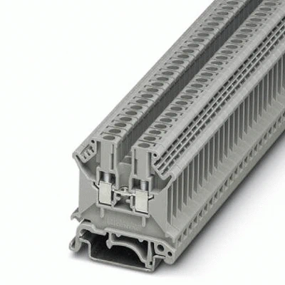
Feed-through terminal block, nom. voltage: 800 V, nominal current: 24 A, connection method: Screw connection, number of connections: 2, cross section: 0.2 mm² – 4 mm², AWG: 24 – 12, width: 5.2 mm, color: gray, mounting type: NS 32, NS 35/15, NS 35/7,5
| Article Number | 3001501 |
|---|---|
| Number of levels | 1 |
| Number of connections | 2 |
| Potentials | 1 |
| Nominal cross section | 2.5 mm² |
| Color | gray |
| Insulating material | PA |
| Flammability rating according to UL 94 | V0 |
| Mounting type | NS 32 |
| Rated surge voltage | 8 kV |
| Degree of pollution | 3 |
| Overvoltage category | III |
| Insulating material group | I |
| Maximum load current | 32 A (with 4 mm² conductor cross section) |
| Nominal current IN | 24 A |
| Nominal voltage UN | 800 V |
| Open side panel | Yes |
| Shock protection test specification | DIN EN 50274 (VDE 0660-514):2002-11 |
| Back of the hand protection | guaranteed |
| Finger protection | guaranteed |
| Result of surge voltage test | Test passed |
| Surge voltage test setpoint | 9.6 kV |
| Result of power-frequency withstand voltage test | Test passed |
| Power frequency withstand voltage setpoint | 2 kV |
| Result of the test for mechanical stability of terminal points (5 x conductor connection) | Test passed |
| Result of flexion and pull-out test | Test passed |
| Bending test rotation speed | 10 rpm |
| Bending test turns | 135 |
| Tensile test result | Test passed |
| Result of tight fit on support | Test passed |
| Tight fit on carrier | NS 32/NS 35 |
| Setpoint | 1 N |
| Result of voltage-drop test | Test passed |
| Requirements, voltage drop | U1 ≤ 3,2 mV U2 ≤ 1,5 x U1 dT ≤ 45 K |
| Result of temperature-rise test | Test passed |
| Requirement temperature-rise test | Increase in temperature ≤ 45 K |
| Short circuit stability result | Test passed |
| Conductor cross section short circuit testing | 2.5 mm² |
| Short-time current | 0.3 kA |
| Result of thermal test | Test passed |
| Proof of thermal characteristics (needle flame) effective duration | 30 s |
| Width | 5.2 mm |
|---|---|
| End cover width | 1.8 mm |
| Length | 42.5 mm |
| Height NS 35/7,5 | 47 mm |
| Height NS 35/15 | 54.5 mm |
| Height NS 32 | 52 mm |
| Connection method | Screw connection |
|---|---|
| Screw thread | M3 |
| Stripping length | 8 mm |
| Tightening torque, min | 0.6 Nm |
| Tightening torque max | 0.8 Nm |
| Connection in acc. with standard | IEC 60947-7-1 |
| Conductor cross section solid min. | 0.2 mm² |
| Conductor cross section solid max. | 4 mm² |
| Conductor cross section AWG min. | 24 |
| Conductor cross section AWG max. | 12 |
| Conductor cross section flexible min. | 0.2 mm² |
| Conductor cross section flexible max. | 2.5 mm² |
| Min. AWG conductor cross section, flexible | 24 |
| Max. AWG conductor cross section, flexible | 14 |
| Conductor cross section flexible, with ferrule without plastic sleeve min. | 0.25 mm² |
| Conductor cross section flexible, with ferrule without plastic sleeve max. | 2.5 mm² |
| Conductor cross section flexible, with ferrule with plastic sleeve min. | 0.25 mm² |
| Conductor cross section flexible, with ferrule with plastic sleeve max. | 1.5 mm² |
| Cross section with insertion bridge, solid max. | 4 mm² |
| Cross section with insertion bridge, stranded max. | 2.5 mm² |
| 2 conductors with same cross section, solid min. | 0.2 mm² |
| 2 conductors with same cross section, solid max. | 1.5 mm² |
| 2 conductors with same cross section, stranded min. | 0.2 mm² |
| 2 conductors with same cross section, stranded max. | 1.5 mm² |
| Two conductors with the same cross section, flexible, with TWIN ferrules, with plastic sleeve, minimum | 0.5 mm² |
| Two conductors with the same cross section, flexible, with TWIN ferrules, with plastic sleeve, maximum | 1 mm² |
| Two conductors with the same cross section stranded, with ferrule and without plastic sleeve, minimum | 0.25 mm² |
| Two conductors with the same cross section stranded, with ferrule and without plastic sleeve, maximum | 1.5 mm² |
| Operating temperature | -60 °C … 105 °C (max. short-term operating temperature 130°C) |
|---|---|
| Ambient temperature (storage/transport) | -25 °C … 60 °C (for a short time, not exceeding 24 h, -60 °C to +70 °C) |
| Permissible humidity (storage/transport) | 30 % … 70 % |
| Ambient temperature (assembly) | -5 °C … 70 °C |
| Ambient temperature (actuation) | -5 °C … 70 °C |
| Connection in acc. with standard | CSA |
|---|---|
| IEC 60947-7-1 | |
| Flammability rating according to UL 94 | V0 |
| REACh SVHC | Lead 7439-92-1 |
|---|---|
| China RoHS | Environmentally Friendly Use Period = 50 years |
| For details about hazardous substances go to tab “Downloads”, Category “Manufacturer’s declaration” |