Inosaki – Your Trusted Phoenix Contact Distributor
Inosaki proudly stands as one of the largest distributors of Phoenix Contact products, offering a comprehensive range of terminal blocks, interface modules, power supplies, and relays.
Series Models: PT Series, ST Series, TB Series, UT Series, and UK Series, PTV Series, UKH Series, Micro Series.
Discover industry-leading Phoenix Contact power supplies, such as:
Get Your Phoenix Contact Catalog Today
Need detailed product information? Contact us at sales@inosaki.com to request your Phoenix Contact catalog.
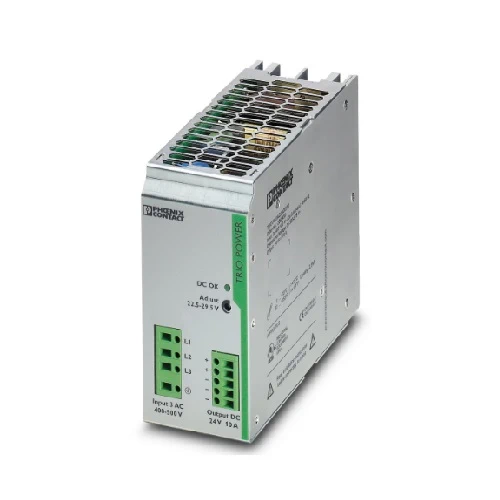
TRIO POWER power supplies with standard functionality
TRIO POWER is particularly suited to standard machine production, thanks to 1- and 3-phase versions up to 960 W. The wide-range input and the international approval package enable worldwide use.
The robust metal housing, the high electric strength, and the wide temperature range ensure a high level of power supply reliability.
| Dimensional drawing | |
| Width | 60 mm |
| Height | 130 mm |
| Depth | 152.5 mm |
| Degree of protection | IP20 |
| Ambient temperature (operation) | -25 °C … 70 °C (> 55° C derating : 2.5%/K) |
| Ambient temperature (storage/transport) | -40 °C … 85 °C |
| Climatic class | 3K3 (in acc. with EN 60721) |
| Max. permissible relative humidity (operation) | ≤ 95 % (at 25 °C, non-condensing) |
| Shock | 18 ms, 30g, in each space direction (according to IEC 60068-2-27) |
| Vibration (operation) | < 15 Hz, amplitude ±2.5 mm (according to IEC 60068-2-6) |
| 15 Hz … 150 Hz, 2.3g, 90 min. |
| AC operation | |
| Nominal input voltage range | 2x / 3x 400 V AC … 500 V AC |
| Input voltage range | 3x 320 V AC … 575 V AC |
| 2x 360 V AC … 575 V AC (for 2-phase operation) | |
| Input voltage range AC | 3x 320 V AC … 575 V AC |
| 2x 360 V AC … 575 V AC (for 2-phase operation) | |
| Voltage type of supply voltage | AC |
| Inrush current | < 15 A |
| Inrush current integral (I2t) | 0.2 A2s |
| AC frequency range | 45 Hz … 65 Hz |
| Mains buffering time | > 20 ms (3x 400 V AC) |
| Current consumption | 3x 0.6 A (400 V AC) |
| 3x 0.5 A (480 V AC) | |
| Nominal power consumption | 456 VA |
| Protective circuit | Transient surge protection; Varistor |
| Power factor (cos phi) | 0.59 |
| Typical response time | < 1 s |
| Strike voltage of gas-filled surge arrester (input to PE) | < |
| Input fuse | < |
| Permissible backup fuse | B6 B10 B16 |
| Permissible DC backup fuse | < |
| Recommended breaker for input protection | < 6 A … 16 A (Characteristics B, C, D, K) |
| Recommended fuse for input protection | < |
| Discharge current to PE | < 3.5 mA |
| Efficiency | 88.5 % (at 400 V AC and nominal values) |
| Output characteristic | U/I |
| Nominal output voltage | 24 V DC ±1 % |
| Setting range of the output voltage (USet) | 22.5 V DC … 29.5 V DC (> 24 V DC, constant capacity restricted) |
| Nominal output current (IN) | 10 A (UOUT = 24 V DC) |
| Derating | 55 °C … 70 °C (2.5%/K) |
| Feedback voltage resistance | 35 V DC |
| Protection against overvoltage at the output (OVP) | < 35 V DC |
| Max. capacitive load | unlimited |
| Active current limitation | approx. 15 A |
| Control deviation | < 1 % (change in load, static 10 % … 90 %) |
| < 2 % (change in load, dynamic 10 % … 90 %) | |
| < 0.1 % (change in input voltage ±10 %) | |
| Residual ripple | < 10 mVPP |
| Output power | 240 W |
| Peak switching voltages nominal load | < 30 mVPP |
| Maximum no-load power dissipation | 7.5 W |
| Power loss nominal load max. | 34 W |
| Rise time | < 2 ms (UOUT (10 % … 90 %)) |
| Connection in parallel | yes, for redundancy and increased capacity |
| Connection in series | yes |
| Item number | 2866459 |
| Packing unit | 1 pc |
| Minimum order quantity | 1 pc |
| Product Key | CMPT33 |
| Catalog Page | Page 177 (C-6-2013) |
| GTIN | 4046356046701 |
| Weight per Piece (including packing) | 1,469.2 g |
| Weight per Piece (excluding packing) | 1,300 g |
| Customs tariff number | 85044083 |
| Country of origin | CN |
| Connection method | Screw connection |
| Conductor cross section, rigid min. | 0.2 mm² |
| Conductor cross section, rigid max. | 2.5 mm² |
| Conductor cross section flexible min. | 0.2 mm² |
| Conductor cross section flexible max. | 2.5 mm² |
| Conductor cross section AWG min. | 24 |
| Conductor cross section AWG max. | 14 |
| Stripping length | 9 mm |
| Screw thread | M2,5 |
| Tightening torque, min | 0.4 Nm |
| Tightening torque max | 0.5 Nm |
| Connection method | Screw connection |
| Conductor cross section, rigid min. | 0.2 mm² |
| Conductor cross section, rigid max. | 2.5 mm² |
| Conductor cross section flexible min. | 0.2 mm² |
| Conductor cross section flexible max. | 2.5 mm² |
| Conductor cross section AWG min. | 16 |
| Conductor cross section AWG max. | 12 |
| Stripping length | 9 mm |
| Screw thread | M2,5 |
| Tightening torque, min | 0.4 Nm |
| Tightening torque max | 0.5 Nm |
| Standard – Electronic equipment for use in electrical power installations and their assembly into electrical power installations | EN 50178/VDE 0160 (PELV) |
| Standard – Limitation of mains harmonic currents | EN 61000-3-2 |
| Standard – Electrical safety | EN 60950-1/VDE 0805 (SELV) |
| Standard – Protection against shock currents, basic requirements for protective separation in electrical equipment | EN 50178 |
| Standard – Safety extra-low voltage | EN 60950-1 (SELV) |
| EN 60204 (PELV) | |
| Standard – Safe isolation | DIN VDE 0100-410 |
| Low Voltage Directive | Conformance with Low Voltage Directive 2014/35/EC |
| EMC requirements for noise emission | EN 61000-6-3 |
| EN 61000-6-4 | |
| EMC requirements for noise immunity | EN 61000-6-1 |
| EN 61000-6-2 | |
| Electromagnetic compatibility | Conformance with EMC Directive 2014/30/EU |
| Electrostatic discharge | |
| Standards/regulations | EN 61000-4-2 |
| Electrostatic discharge | |
| Contact discharge | 8 kV (Test Level 4) |
| Discharge in air | 8 kV (Test Level 3) |
| Comments | Criterion A |
| Electromagnetic HF field | |
| Standards/regulations | EN 61000-4-3 |
| Electromagnetic HF field | |
| Frequency range | 80 MHz … 1 GHz |
| Test field strength | 10 V/m |
| Frequency range | 1 GHz … 2 GHz |
| Test field strength | 10 V/m |
| Frequency range | 2 GHz … 3 GHz |
| Test field strength | 10 V/m |
| Comments | Criterion A |
| Fast transients (burst) | |
| Standards/regulations | EN 61000-4-4 |
| Fast transients (burst) | |
| Input | 4 kV (Test Level 4 – asymmetrical) |
| Output | 4 kV (Test Level 4 – asymmetrical) |
| Signal | 2 kV (Test Level 3 – asymmetrical) |
| Comments | Criterion A |
| Surge voltage load (surge) | |
| Standards/regulations | EN 61000-4-5 |
| Input | 2 kV (Test Level 3 – symmetrical) |
| 4 kV (Test Level 4 – asymmetrical) | |
| Output | 1 kV (Test Level 2 – symmetrical) |
| 2 kV (Test Level 3 – asymmetrical) | |
| Comments | Criterion A |
| Conducted interference | |
| Standards/regulations | EN 61000-4-6 |
| Conducted interference | |
| Frequency range | 0.15 MHz … 80 MHz |
| Comments | Criterion A |
| Voltage | 10 V (Test Level 3) |
| Voltage dips | |
| Standards/regulations | EN 61000-4-11 |
| Emitted interference | |
| Standards/regulations | EN 61000-6-3 |
| Radio interference voltage in acc. with EN 55011 | EN 55011 (EN 55022) Class B, area of application: Industry and residential |
| Emitted radio interference in acc. with EN 55011 | EN 55011 (EN 55022) Class B, area of application: Industry and residential |
| Criteria | |
| Criterion A | Normal operating behavior within the specified limits. |
| Criterion B | Temporary impairment to operational behavior that is corrected by the device itself. |