USD 620.88
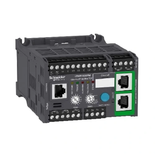
TeSys T is a motor management system that provides full motor monitoring, control, and protection when used with short circuit protection and a contactor. TeSys T manages most critical processes while reducing downtime and increasing productivity. TeSys T is a flexible system that integrates seamlessly into your automation system through five major communication protocols. TeSys T predicts what will happen in the process, as it accurately monitors current, voltage, and power over a wide range. This controller is the central component in the motor management system. The module manages the basic functions of the motor management system. It manages the measurement of 3 phase current via integral current transformers from 0.4 to 100 A or up to 810 A by external current transformers. It also measures ground current with internal or external ground sensors, motor temperature and the inputs and outputs for the various motor control modes, detected fault management and other functions. Ethernet/IP and Modbus/TCP protocol is used by this controller. Ethernet TCP/IP communication is used. This module has 6 discrete logic inputs, 3 relay logic outputs and a relay output for detected fault signaling overload relay. The current range of this controller is 5 to 100 amperes. 120 to 240 VAC is used to power this controller. Controller has the following certifications: UL, CSA NOM, ATEX, BV, EAC, RINA, LROS, DNV, ABS, GL, KERI, RMRoS, C-Tick and CCC.
| Main | |
| Part Number |
LTMR100EFM |
| Range | TeSys |
| Product name | TeSys T |
| Device short name | LTMR |
| Product or component type | Motor controller |
| Device application | Equipment monitoring and control |
| Measurement current | 5…100 A |
| [Us] rated supply voltage | 100…240 V AC 50/60 Hz |
| Current consumption | 8…62.8 mA |
| supply voltage limits | 93.5…264 V AC |
| Communication port protocol | Modbus TCP/EtherNet/IP |
| bus type | Ethernet IEEE 802.3 interface, addressing 0…159, transmission rate 10…100 Mbit/s, RJ45 with 2 shielded twisted pairs |
| Complementary | |
| [Ui] rated insulation voltage | 690 V conforming to EN/IEC 60947-1 |
| 690 V conforming to CSA C22.2 No 14 | |
| 690 V conforming to UL 508 | |
| [Uimp] rated impulse withstand voltage | 4 kV supply, inputs and outputs conforming to EN/IEC 60947-4-1 |
| 6 kV current or voltage measurement circuit conforming to EN/IEC 60947-4-1 | |
| 0.8 kV communication circuit conforming to EN/IEC 60947-4-1 | |
| short-circuit withstand | 100 kA conforming to EN/IEC 60947-4-1 |
| associated fuse rating | 4 A gG for output |
| 0.5 A gG for control circuit | |
| protection type | Reverse polarity protection |
| Overload | |
| Phase unbalance | |
| Overload (long time) | |
| Thermal protection | |
| Power factor variation | |
| Thermal overload protection | |
| Locked rotor | |
| Earth-leakage protection | |
| Load fluctuation | |
| Phase failure | |
| Network and machine diagnosis type | Waiting time after overload tripping |
| Motor control command recording | |
| Trip context information | |
| Phase fault and earth fault trip counters | |
| Starting current and time | |
| Trip history information | |
| Fault recording | |
| Event recording | |
| Remaining operating time before overload tripping | |
| Running hours counter/operating time | |
| Logic input number | 6 |
| input current | 3.1 mA at 100 V |
| 7.5 mA at 240 V | |
| current state 0 guaranteed | Logic input: 0…40 V and <= 15 mA for 25 ms |
| current state 1 guaranteed | Logic input: 79…264 V and >= 2 mA for 25 ms |
| maximum output switching frequency | 2 Hz |
| load current | 5 A at 250 V AC for logic output |
| 5 A at 30 V DC for logic output | |
| permissible power | 480 VA (AC-15), Ie = 2 A, 500000 cycles (output) |
| 30 W (DC-13), Ie = 1.25 A, 500000 cycles (output) | |
| Maximum operating rate | 1800 cyc/h |
| contacts type and composition | 1 NO + 1 NC fault signal |
| 3 NO | |
| Metering type | Phase current I1, I2, I3 RMS |
| Temperature | |
| Earth-fault current | |
| Average current Iavg | |
| Imbalance current | |
| measurement accuracy | 5…15 % earth fault current internal measurement |
| 1 % voltage (100…830 V) | |
| 3 % power factor | |
| 5 % earth fault current external measurement | |
| +/- 30 min/year internal clock | |
| 0,02 temperature | |
| 5 % active and reactive power | |
| 0,02 current | |
| Overvoltage category | III |
| Connection pitch | 5.08 mm |
| connections – terminals | Control circuit: connector 1 cable(s) 0.25…2.5 mm² (AWG 24…AWG 14) flexible with cable end |
| Control circuit: connector 1 cable(s) 0.2…2.5 mm² (AWG 24…AWG 14) flexible without cable end | |
| Control circuit: connector 1 cable(s) 0.25…2.5 mm² (AWG 24…AWG 14) flexible without cable end | |
| Control circuit: connector 1 cable(s) 0.2…2.5 mm² (AWG 24…AWG 14) solid without cable end | |
| Control circuit: connector 2 cable(s) 0.2…1 mm² (AWG 24…AWG 14) flexible with cable end | |
| Control circuit: connector 2 cable(s) 0.2…1.5 mm² (AWG 24…AWG 14) flexible without cable end | |
| Control circuit: connector 2 cable(s) 0.5…1.5 mm² (AWG 24…AWG 14) flexible without cable end | |
| Control circuit: connector 2 cable(s) 0.2…1 mm² (AWG 24…AWG 14) solid without cable end | |
| tightening torque | Control circuit: 0.5…0.6 N.m flat screwdriver 3 mm |
| Pollution degree | 3 |
| electromagnetic compatibility | Electrostatic discharge, 3, 8 kV air, 6 kV contact, conforming to EN/IEC 61000-4-2 |
| Radiated RF fields, 3, 10 V/m, conforming to EN/IEC 61000-4-3 | |
| Fast transients immunity test (other circuits), level 3, 2 kV, conforming to EN/IEC 61000-4-4 | |
| Fast transients immunity test (on supply and relay outputs), level 4, 4 kV, conforming to EN/IEC 61000-4-4 | |
| Voltage dips and interruptions immunity test, 70 %, 500 ms, conforming to EN/IEC 61000-4-11 | |
| Conducted RF disturbances, 10 V, conforming to EN/IEC 61000-4-6 | |
| Temperature sensor: surges (serial mode), 0.5 kV, conforming to EN/IEC 61000-4-5 | |
| Temperature sensor: surges (common mode), 1 kV, conforming to EN/IEC 61000-4-5 | |
| Control circuit: surges (serial mode), 1 kV, conforming to EN/IEC 61000-4-5 | |
| Communication: surges (common mode), 2 kV, conforming to EN/IEC 61000-4-5 | |
| Relay outputs and supply: surges (serial mode), 2 kV, conforming to EN/IEC 61000-4-5 | |
| Relay outputs and supply: surges (common mode), 4 kV, conforming to EN/IEC 61000-4-5 | |
| Control circuit: surges (common mode), 2 kV, conforming to EN/IEC 61000-4-5 | |
| Width | 91 mm |
| Height | 61 mm |
| Depth | 122.5 mm |
| Net weight | 0.53 kg |
| Web services | Web server |
| Compatibility code | LTMR |
| Environment | |
| Standards | CSA C22.2 No 14 |
| EN 60947-4-1 | |
| IACS E10 | |
| UL 508 | |
| IEC 60947-4-1 | |
| Product certifications | C-Tick |
| ABS | |
| UL | |
| DNV | |
| NOM | |
| RINA | |
| RMRoS | |
| BV | |
| LROS (Lloyds register of shipping) | |
| KERI | |
| EAC | |
| CCC | |
| CSA | |
| ATEX | |
| GL | |
| protective treatment | 12 x 24 hour cycles conforming to EN/IEC 60068-2-30 |
| 48 h conforming to EN/IEC 60070-2-11 | |
| TH conforming to EN/IEC 60068 | |
| fire resistance | 650 °C conforming to EN/IEC 60695-2-12 |
| 960 °C conforming to UL 94 | |
| ambient air temperature for operation | -20…60 °C |
| Ambient air temperature for storage | -40…80 °C |
| operating altitude | <= 2000 m without derating |
| mechanical robustness | Vibrations mounted on symmetrical rail: 1 Gn, 5…300 Hz conforming to EN/IEC 60068-2-6 |
| Vibrations plate mounted: 4 Gn, 5…300 Hz conforming to EN/IEC 60068-2-6 | |
| Shocks half sine wave acceleration: 15 Gn for 11 ms conforming to EN/IEC 60068-2-27 | |
| IP degree of protection | IP20 |
| Packing Units | |
| Unit Type of Package 1 | PCE |
| Number of Units in Package 1 | 1 |
| Package 1 Height | 7.2 cm |
| Package 1 Width | 10.0 cm |
| Package 1 Length | 13.5 cm |
| Package 1 Weight | 538.0 g |
| Unit Type of Package 2 | S02 |
| Number of Units in Package 2 | 10 |
| Package 2 Height | 15.0 cm |
| Package 2 Width | 30.0 cm |
| Package 2 Length | 40.0 cm |
| Package 2 Weight | 5.685 kg |
| Contractual warranty | |
| Warranty | 18 months |