USD 30.68
Inosaki – Your Trusted Phoenix Contact Distributor
Inosaki proudly stands as one of the largest distributors of Phoenix Contact products, offering a comprehensive range of terminal blocks, interface modules, power supplies, and relays.
Series Models: PT Series, ST Series, TB Series, UT Series, and UK Series, PTV Series, UKH Series, Micro Series.
Discover industry-leading Phoenix Contact power supplies, such as:
Get Your Phoenix Contact Catalog Today
Need detailed product information? Contact us at sales@inosaki.com to request your Phoenix Contact catalog.
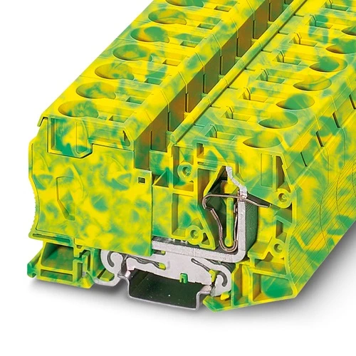
| Item number | 3036194 |
| Packing unit | 10 pc |
| Minimum order quantity | 1 pc |
| Product key | BE2121 |
| Catalog page | Page 249 (C-1-2019) |
| GTIN | 4017918876760 |
| Weight per piece (including packing) | 105.52 g |
| Weight per piece (excluding packing) | 105.52 g |
| Customs tariff number | 85369010 |
| Country of origin | PL |
| Product type | Ground terminal block |
| Number of connections | 2 |
| Number of rows | 1 |
| Potentials | 1 |
| Insulation characteristics | |
| Overvoltage category | III |
| Degree of pollution | 3 |
| Rated surge voltage | 8 kV |
| Maximum power dissipation for nominal condition | 4.06 W |
| Number of connections per level | 2 |
| Nominal cross section | 35 mm² |
| 1 level | |
| Stripping length | 25 mm |
| Internal cylindrical gage | A8 |
| Connection in acc. with standard | IEC 60947-7-1 |
| Conductor cross section rigid | 2.5 mm² … 35 mm² |
| Cross section AWG | 12 … 2 (converted acc. to IEC) |
| Conductor cross section flexible | 2.5 mm² … 35 mm² |
| Conductor cross section, flexible [AWG] | 12 … 2 (converted acc. to IEC) |
| Conductor cross-section flexible (ferrule without plastic sleeve) | 2.5 mm² … 35 mm² |
| Flexible conductor cross section (ferrule with plastic sleeve) | 2.5 mm² … 35 mm² |
| Nominal current | 125 A |
| Maximum load current | 125 A (with 35 mm² conductor cross section) |
| Nominal voltage | 1000 V |
| Note | The supply from the ST 35 terminal block to the ST 16 TWIN terminal block with the RB-ST 35 reducing bridge is single-sided only. In the case of a central supply, the D-ST 16-TWIN cover cannot be bridged via the reducing bridge. |
| Nominal cross section | 35 mm² |
| Rated data (ATEX/IECEx) | |
| Identification | II 2 GD Ex eb IIC Gb |
| Operating temperature range | -60 °C … 85 °C |
| Ex-certified accessories | 1206612 SZF 3-1,0X5,5 |
| 3022276 CLIPFIX 35-5 | |
| 3022218 CLIPFIX 35 | |
| output | (Permanent) |
| Ex connection data General | |
| Nominal cross section | 35 mm² |
| Rated cross section AWG | 2 |
| Connection capacity rigid | 2.5 mm² … 35 mm² |
| Connection capacity AWG | 14 … 2 |
| Connection capacity flexible | 2.5 mm² … 35 mm² |
| Connection capacity AWG | 14 … 2 |
| Width | 16 mm |
| Height | 100 mm |
| Depth on NS 35/7,5 | 59 mm |
| Depth on NS 35/15 | 66.5 mm |
| Color | green-yellow |
| Flammability rating according to UL 94 | V0 |
| Insulating material group | I |
| Insulating material | PA |
| Static insulating material application in cold | -60 °C |
| Temperature index of insulation material (DIN EN 60216-1 (VDE 0304-21)) | 125 °C |
| Relative insulation material temperature index (Elec., UL 746 B) | 130 °C |
| Fire protection for rail vehicles (DIN EN 45545-2) R22 | HL 1 – HL 3 |
| Fire protection for rail vehicles (DIN EN 45545-2) R23 | HL 1 – HL 3 |
| Fire protection for rail vehicles (DIN EN 45545-2) R24 | HL 1 – HL 3 |
| Fire protection for rail vehicles (DIN EN 45545-2) R26 | HL 1 – HL 3 |
| Calorimetric heat release NFPA 130 (ASTM E 1354) | 27,5 MJ/kg |
| Surface flammability NFPA 130 (ASTM E 162) | passed |
| Specific optical density of smoke NFPA 130 (ASTM E 662) | passed |
| Smoke gas toxicity NFPA 130 (SMP 800C) | passed |
| Mechanical data | |
| Open side panel | No |
| Oscillation/broadband noise | |
| Specification | DIN EN 50155 (VDE 0115-200):2008-03 |
| Spectrum | Long life test category 2, bogie-mounted |
| Frequency | f1 = 5 Hz to f2 = 250 Hz |
| ASD level | 6.12 (m/s²)²/Hz |
| Acceleration | 3.12g |
| Test duration per axis | 5 h |
| Test directions | X-, Y- and Z-axis |
| Result | Test passed |
| Shocks | |
| Specification | DIN EN 50155 (VDE 0115-200):2008-03 |
| Pulse shape | Half-sine |
| Acceleration | 30g |
| Shock duration | 18 ms |
| Number of shocks per direction | 3 |
| Test directions | X-, Y- and Z-axis (pos. and neg.) |
| Result | Test passed |
| Ambient conditions | |
| Ambient temperature (operation) | -60 °C … 110 °C (Operating temperature range incl. self-heating; for max. short-term operating temperature, see RTI Elec.) |
| Ambient temperature (storage/transport) | -25 °C … 60 °C (for a short time, not exceeding 24 h, -60 °C to +70 °C) |
| Ambient temperature (assembly) | -5 °C … 70 °C |
| Ambient temperature (actuation) | -5 °C … 70 °C |
| Permissible humidity (operation) | 20 % … 90 % |
| Permissible humidity (storage/transport) | 30 % … 70 % |
| Connection in acc. with standard | IEC 60947-7-1 |
| Mounting type | NS 35/7,5 |
| NS 35/15 |