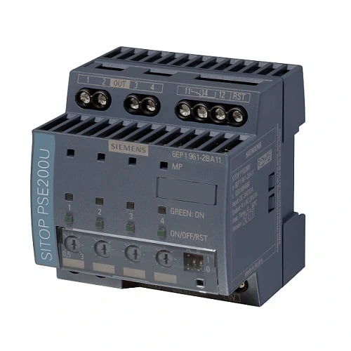
The SITOP PSE200U and SITOP SEL1200/SEL1400 selectivity modules are the optimal expansion for all 24 V power supplies in order to distribute the load current across multiple feeders and monitor it. Overload and short-circuit in one or more feeders is reliably detected and signaled.
| Article number | 6EP1961-2BA11 | |
| product brand name | SITOP PSE200U | |
| type of current supply | Selectivity module, 4 x 3 A Common signal contact | |
| Input | ||
| type of the power supply network | Controlled DC voltage | |
| supply voltage at DC rated value | 24 V | |
| input voltage at DC | 22 … 30 V | |
| overvoltage overload capability | 35 V | |
| input current at rated input voltage 24 V rated value | 12 A | |
| Output | ||
| voltage curve at output | controlled DC voltage | |
| formula for output voltage | Vin – approx. 0.2 V | |
| relative overall tolerance of the voltage note | In accordance with the supplying input voltage | |
| number of outputs | 4 | |
| output current up to 60 °C per output rated value | 3 A | |
| adjustable current response value current of the current-dependent overload release | 0.5 … 3 A | |
| type of response value setting | via potentiometer | |
| product feature parallel switching of outputs | No | |
| type of outputs connection | Simultaneous connection of all outputs after power up of the supply voltage > 20 V, delay time of 25 ms, 100 ms or adjustable “load optimised” via DIP switch for sequential connection | |
| Efficiency | ||
| efficiency in percent | 97 % | |
| power loss [W] at rated output voltage for rated value of the output current typical | 9 W | |
| Switch-off characteristic per output | ||
| switching characteristic | ||
| ● of the excess current | Iout = 1.0 …1.5 x set value, switch-off after approx. 5 s | |
| ● of the current limitation | Iout = 1.5 x set value, switch-off after typ. 100 ms | |
| ● of the immediate switch-off | Iout > set value and Vin < 20 V, switch-off after approx. 0.5 ms | |
| residual current at switch-off typical | 1 mA | |
| design of the reset device/resetting mechanism | via sensor per output | |
| remote reset function | Non-electrically isolated 24 V input (signal level “high” at > 15 V) | |
| Protection and monitoring | ||
| fuse protection type at input | 5 A per output (not accessible) | |
| display version for normal operation | Three-color LED per output: green LED for “Output switched through”; yellow LED for “Output switched off manually”; red LED for “Output switched off due to overcurrent” | |
| design of the switching contact for signaling function | Common signal contact (changeover contact, rating 0.1 A/24 V DC) | |
| Safety | ||
| galvanic isolation between input and output at switch-off | No | |
| standard for safety | according to EN 60950-1 and EN 50178 | |
| operating resource protection class | Class III | |
| protection class IP | IP20 | |
| Approvals | ||
| certificate of suitability | ||
| ● CE marking | Yes | |
| ● UL approval | Yes; UL-Recognized (UL 2367) File E328600; cULus-Listed (UL 508, CSA C22.2 No. 107.1) File E197259 | |
| ● ATEX | No | |
| certificate of suitability | ||
| ● IECEx | No | |
| certificate of suitability | ||
| ● EAC approval | Yes | |
| ● shipbuilding approval | Yes | |
| shipbuilding approval | DNV GL, ABS | |
| Marine classification association | ||
| ● American Bureau of Shipping Europe Ltd. (ABS) | Yes | |
| ● DNV GL | Yes | |
| EMC | ||
| standard | ||
| ● for emitted interference | EN 55022 Class B | |
| ● for interference immunity | EN 61000-6-2 | |
| environmental conditions | ||
| ambient temperature | ||
| ● during operation | -25 … +60 °C; with natural convection | |
| ● during transport | -40 … +85 °C | |
| ● during storage | -40 … +85 °C | |
| environmental category according to IEC 60721 | Climate class 3K3, 5 … 95% no condensation | |
| Mechanics | ||
| type of electrical connection | screw-type terminals | |
| ● at input | +24 V: 2 screw terminals for 0.5 … 16 mm²; 0 V: 2 screw terminals for 0.5 … 4 mm² | |
| ● at output | Output 1 … 4: 1 screw terminal each for 0.5 … 4 mm² | |
| ● for signaling contact | 3 screw terminals for 0.5 … 4 mm² | |
| ● for auxiliary contacts | Remote reset: 1 screw terminal for 0.5 … 4 mm² | |
| width of the enclosure | 72 mm | |
| height of the enclosure | 80 mm | |
| depth of the enclosure | 72 mm | |
| installation width | 72 mm | |
| mounting height | 180 mm | |
| required spacing | ||
| ● top | 50 mm | |
| ● bottom | 50 mm | |
| ● left | 0 mm | |
| ● right | 0 mm | |
| net weight | 0.2 kg | |
| fastening method | Snaps onto DIN rail EN 60715 35×7.5/15 | |
| mechanical accessories | Device identification label 20 mm × 7 mm, TI-grey 3RT2900-1SB20 | |
| MTBF at 40 °C | 755 915 h | |
| other information | Specifications at rated input voltage and ambient temperature +25 °C (unless otherwise specified) | |