USD 43.42 – USD 100.10Price range: USD 43.42 through USD 100.10
| Part number | 3RV6021-4AA15 | 3RV6021-4BA15 | 3RV6021-4CA15 | 3RV6021-4DA15 |
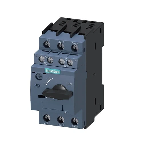
| product brand name | SIRIUS | SIRIUS | SIRIUS | SIRIUS |
| product designation | Circuit breaker | Circuit breaker | Circuit breaker | Circuit breaker |
| design of the product | for motor protection | for motor protection | for motor protection | for motor protection |
| product type designation | 3RV6 | 3RV6 | 3RV6 | 3RV6 |
| General technical data | ||||
| size of the circuit-breaker | S0 | S0 | S0 | S0 |
| power loss [W] total typical | 7 W | 8 W | 8 W | 8 W |
| insulation voltage with degree of pollution 3 at AC rated value | 690 V | 690 V | 690 V | 690 V |
| surge voltage resistance rated value | 6 kV | 6 kV | 6 kV | 6 kV |
| shock resistance according to IEC 60068-2-27 | 25g / 11 ms | 25g / 11 ms | 25g / 11 ms | 25g / 11 ms |
| Substance Prohibitance (Date) | 5/1/2012 | 5/1/2012 | 5/1/2012 | 5/1/2012 |
| Ambient conditions | ||||
| installation altitude at height above sea level maximum | 2 000 m | 2 000 m | 2 000 m | 2 000 m |
| ambient temperature | ||||
| ? during operation | -20 … +60 °C | -20 … +60 °C | -20 … +60 °C | -20 … +60 °C |
| ? during transport | -50 … +80 °C | -50 … +80 °C | -50 … +80 °C | -50 … +80 °C |
| relative humidity during operation | 10 … 95 % | 10 … 95 % | 10 … 95 % | 10 … 95 % |
| Main circuit | ||||
| number of poles for main current circuit | 3 | 3 | 3 | 3 |
| adjustable current response value current of the current-dependent overload release | 10 … 16 A | 13 … 20 A | 16 … 22 A | 18 … 25 A |
| operating voltage | ||||
| rated value | 690 V | 690 V | 690 V | 690 V |
| at AC-3 rated value maximum | 690 V | 690 V | 690 V | 690 V |
| operating frequency rated value | 50 … 60 Hz | 50 … 60 Hz | 50 … 60 Hz | 50 … 60 Hz |
| operational current rated value 25 A | 16 A | 20 A | 22 A | 25 A |
| operational current at AC-3 at 400 V rated value | 16 A | 20 A | 22 A | 25 A |
| operating frequency at AC-3 maximum | 15 1/h | 15 1/h | 15 1/h | 15 1/h |
| Auxiliary circuit | ||||
| design of the auxiliary switch | transverse | transverse | transverse | transverse |
| Protective and monitoring functions | ||||
| trip class | CLASS 10 | CLASS 10 | CLASS 10 | CLASS 10 |
| design of the overload release | thermal | thermal | thermal | thermal |
| maximum short-circuit current breaking capacity (Icu) at AC at 400 V rated value | 55 kA | 55 kA | 55 kA | 55 kA |
| operating short-circuit current breaking capacity (Ics) at AC at 400 V rated value | 25 kA | 25 kA | 25 kA | 25 kA |
| response value current of instantaneous short-circuit trip unit | 208 A | 260 A | 286 A | 325 A |
| Short-circuit protection | ||||
| product function short circuit protection | Yes | Yes | Yes | Yes |
| design of the short-circuit trip | magnetic | magnetic | magnetic | magnetic |
| Installation/ mounting/ dimensions | ||||
| mounting position | any | any | any | any |
| fastening method | screw and snap-on mounting onto 35 mm DIN rail according to DIN EN60715 | screw and snap-on mounting onto 35 mm DIN rail according to DIN EN60715 | screw and snap-on mounting onto 35 mm DIN rail according to DIN EN60715 | screw and snap-on mounting onto 35 mm DIN rail according to DIN EN60715 |
| height | 97 mm | 97 mm | 97 mm | 97 mm |
| width | 45 mm | 45 mm | 45 mm | 45 mm |
| depth | 96 mm | 96 mm | 96 mm | 96 mm |
| required spacing for grounded parts | ||||
| forwards | 0 mm | 0 mm | 0 mm | 0 mm |
| backwards | 0 mm | 0 mm | 0 mm | 0 mm |
| upwards | 50 mm | 50 mm | 50 mm | 50 mm |
| at the side | 30 mm | 30 mm | 30 mm | 30 mm |
| downwards | 50 mm | 50 mm | 50 mm | 50 mm |
| Connections/ Terminals | ||||
| type of electrical connection | ||||
| for main current circuit | screw-type terminals | screw-type terminals | screw-type terminals | screw-type terminals |
| for auxiliary and control circuit | screw-type terminals | screw-type terminals | screw-type terminals | screw-type terminals |
| arrangement of electrical connectors for main current circuit | Top and bottom | Top and bottom | Top and bottom | Top and bottom |
| type of connectable conductor cross-sections | ||||
| for main contacts | ||||
| — solid or stranded | 2x (1 … 2.5 mm²), 2x (2.5 … 10 mm²) | 2x (1 … 2.5 mm²), 2x (2.5 … 10 mm²) | 2x (1 … 2.5 mm²), 2x (2.5 … 10 mm²) | 2x (1 … 2.5 mm²), 2x (2.5 … 10 mm²) |
| — finely stranded with core end processing | 2x (1 … 2.5 mm²), 2x (2.5 … 6 mm²), 1x 10 mm² | 2x (1 … 2.5 mm²), 2x (2.5 … 6 mm²), 1x 10 mm² | 2x (1 … 2.5 mm²), 2x (2.5 … 6 mm²), 1x 10 mm² | 2x (1 … 2.5 mm²), 2x (2.5 … 6 mm²), 1x 10 mm² |
| at AWG cables for main contacts | 2x (16 … 12), 2x (14 … 8) | 2x (16 … 12), 2x (14 … 8) | 2x (16 … 12), 2x (14 … 8) | 2x (16 … 12), 2x (14 … 8) |
| type of connectable conductor cross-sections | ||||
| for auxiliary contacts | ||||
| — solid or stranded | 2x (0.5 … 1.5 mm²), 2x (0.75 … 2.5 mm²) | 2x (0.5 … 1.5 mm²), 2x (0.75 … 2.5 mm²) | 2x (0.5 … 1.5 mm²), 2x (0.75 … 2.5 mm²) | 2x (0.5 … 1.5 mm²), 2x (0.75 … 2.5 mm²) |
| — finely stranded with core end processing | 2x (0.5 … 1.5 mm²), 2x (0.75 … 2.5 mm²) | 2x (0.5 … 1.5 mm²), 2x (0.75 … 2.5 mm²) | 2x (0.5 … 1.5 mm²), 2x (0.75 … 2.5 mm²) | 2x (0.5 … 1.5 mm²), 2x (0.75 … 2.5 mm²) |
| at AWG cables for main contacts | 2x (20 … 16), 2x (18 … 14) | 2x (20 … 16), 2x (18 … 14) | 2x (20 … 16), 2x (18 … 14) | 2x (20 … 16), 2x (18 … 14) |
| tightening torque | ||||
| for main contacts with screw-type terminals | 2 … 2.5 N·m | 2 … 2.5 N·m | 2 … 2.5 N·m | 2 … 2.5 N·m |
| for auxiliary contacts with screw-type terminals | 0.8 … 1.2 N·m | 0.8 … 1.2 N·m | 0.8 … 1.2 N·m | 0.8 … 1.2 N·m |
| Safety related data | ||||
| protection class IP on the front according to IEC 60529 | IP20 | IP20 | IP20 | IP20 |
| touch protection on the front according to IEC 60529 | finger-safe, for vertical contact from the front | finger-safe, for vertical contact from the front | finger-safe, for vertical contact from the front | finger-safe, for vertical contact from the front |
| Part number | 3RV6021-4EA15 | 3RV6021-4FA15 | 3RV6021-4NA15 | 3RV6021-4PA15 |
| product brand name | SIRIUS | SIRIUS | SIRIUS | SIRIUS |
| product designation | Circuit breaker | Circuit breaker | Circuit breaker | Circuit breaker |
| design of the product | for motor protection | for motor protection | for motor protection | for motor protection |
| product type designation | 3RV6 | 3RV6 | 3RV6 | 3RV6 |
| General technical data | ||||
| size of the circuit-breaker | S0 | S0 | S0 | S0 |
| power loss [W] total typical | 11 W | 14 W | 11 W | 14 W |
| insulation voltage with degree of pollution 3 at AC rated value | 690 V | 690 V | 690 V | 690 V |
| surge voltage resistance rated value | 6 kV | 6 kV | 6 kV | 6 kV |
| shock resistance according to IEC 60068-2-27 | 25g / 11 ms | 25g / 11 ms | 25g / 11 ms | 25g / 11 ms |
| Substance Prohibitance (Date) | 5/1/2012 | 5/1/2012 | 5/1/2012 | 5/1/2012 |
| Ambient conditions | ||||
| installation altitude at height above sea level maximum | 2 000 m | 2 000 m | 2 000 m | 2 000 m |
| ambient temperature | ||||
| ? during operation | -20 … +60 °C | -20 … +40 °C | -20 … +60 °C | -20 … +40 °C |
| ? during transport | -50 … +80 °C | -50 … +80 °C | -50 … +80 °C | -50 … +80 °C |
| relative humidity during operation | 10 … 95 % | 10 … 95 % | 10 … 95 % | 10 … 95 % |
| Main circuit | ||||
| number of poles for main current circuit | 3 | 3 | 3 | 3 |
| adjustable current response value current of the current-dependent overload release | 27 … 32 A | 34 … 40 A | 23 … 28 A | 30 … 36 A |
| operating voltage | ||||
| rated value | 690 V | 690 V | 690 V | 690 V |
| at AC-3 rated value maximum | 690 V | 690 V | 690 V | 690 V |
| operating frequency rated value | 50 … 60 Hz | 50 … 60 Hz | 50 … 60 Hz | 50 … 60 Hz |
| operational current rated value 25 A | 32 A | 40 A | 28 A | 36 A |
| operational current at AC-3 at 400 V rated value | 32 A | 40 A | 28 A | 36 A |
| operating frequency at AC-3 maximum | 15 1/h | 15 1/h | 15 1/h | 15 1/h |
| Auxiliary circuit | ||||
| design of the auxiliary switch | transverse | transverse | transverse | transverse |
| Protective and monitoring functions | ||||
| trip class | CLASS 10 | CLASS 10 | CLASS 10 | CLASS 10 |
| design of the overload release | thermal | thermal | thermal | thermal |
| maximum short-circuit current breaking capacity (Icu) at AC at 400 V rated value | 55 kA | 20 kA | 55 kA | 20 kA |
| operating short-circuit current breaking capacity (Ics) at AC at 400 V rated value | 25 kA | 10 kA | 25 kA | 10 kA |
| response value current of instantaneous short-circuit trip unit | 400 A | 480 A | 364 A | 432 A |
| Short-circuit protection | ||||
| product function short circuit protection | Yes | Yes | Yes | Yes |
| design of the short-circuit trip | magnetic | magnetic | magnetic | magnetic |
| Installation/ mounting/ dimensions | ||||
| mounting position | any | any | any | any |
| fastening method | screw and snap-on mounting onto 35 mm DIN rail according to DIN EN60715 | screw and snap-on mounting onto 35 mm DIN rail according to DIN EN60715 | screw and snap-on mounting onto 35 mm DIN rail according to DIN EN60715 | screw and snap-on mounting onto 35 mm DIN rail according to DIN EN60715 |
| height | 97 mm | 97 mm | 97 mm | 97 mm |
| width | 45 mm | 45 mm | 45 mm | 45 mm |
| depth | 96 mm | 96 mm | 96 mm | 96 mm |
| required spacing for grounded parts | ||||
| forwards | 0 mm | 0 mm | 0 mm | 0 mm |
| backwards | 0 mm | 0 mm | 0 mm | 0 mm |
| upwards | 50 mm | 70 mm | 50 mm | 70 mm |
| at the side | 30 mm | 30 mm | 30 mm | 30 mm |
| downwards | 50 mm | 70 mm | 50 mm | 70 mm |
| Connections/ Terminals | ||||
| type of electrical connection | ||||
| for main current circuit | screw-type terminals | screw-type terminals | screw-type terminals | screw-type terminals |
| for auxiliary and control circuit | screw-type terminals | screw-type terminals | screw-type terminals | screw-type terminals |
| arrangement of electrical connectors for main current circuit | Top and bottom | Top and bottom | Top and bottom | Top and bottom |
| type of connectable conductor cross-sections | ||||
| for main contacts | ||||
| — solid or stranded | 2x (1 … 2.5 mm²), 2x (2.5 … 10 mm²) | 2x (1 … 2.5 mm²), 2x (2.5 … 10 mm²) | 2x (1 … 2.5 mm²), 2x (2.5 … 10 mm²) | 2x (1 … 2.5 mm²), 2x (2.5 … 10 mm²) |
| — finely stranded with core end processing | 2x (1 … 2.5 mm²), 2x (2.5 … 6 mm²), 1x 10 mm² | 2x (1 … 2.5 mm²), 2x (2.5 … 6 mm²), 1x 10 mm² | 2x (1 … 2.5 mm²), 2x (2.5 … 6 mm²), 1x 10 mm² | 2x (1 … 2.5 mm²), 2x (2.5 … 6 mm²), 1x 10 mm² |
| at AWG cables for main contacts | 2x (16 … 12), 2x (14 … 8) | 2x (16 … 12), 2x (14 … 8) | 2x (16 … 12), 2x (14 … 8) | 2x (16 … 12), 2x (14 … 8) |
| type of connectable conductor cross-sections | ||||
| for auxiliary contacts | ||||
| — solid or stranded | 2x (0.5 … 1.5 mm²), 2x (0.75 … 2.5 mm²) | 2x (0.5 … 1.5 mm²), 2x (0.75 … 2.5 mm²) | 2x (0.5 … 1.5 mm²), 2x (0.75 … 2.5 mm²) | 2x (0.5 … 1.5 mm²), 2x (0.75 … 2.5 mm²) |
| — finely stranded with core end processing | 2x (0.5 … 1.5 mm²), 2x (0.75 … 2.5 mm²) | 2x (0.5 … 1.5 mm²), 2x (0.75 … 2.5 mm²) | 2x (0.5 … 1.5 mm²), 2x (0.75 … 2.5 mm²) | 2x (0.5 … 1.5 mm²), 2x (0.75 … 2.5 mm²) |
| at AWG cables for main contacts | 2x (20 … 16), 2x (18 … 14) | 2x (20 … 16), 2x (18 … 14) | 2x (20 … 16), 2x (18 … 14) | 2x (20 … 16), 2x (18 … 14) |
| tightening torque | ||||
| for main contacts with screw-type terminals | 2 … 2.5 N·m | 2 … 2.5 N·m | 2 … 2.5 N·m | 2 … 2.5 N·m |
| for auxiliary contacts with screw-type terminals | 0.8 … 1.2 N·m | 0.8 … 1.2 N·m | 0.8 … 1.2 N·m | 0.8 … 1.2 N·m |
| Safety related data | ||||
| protection class IP on the front according to IEC 60529 | IP20 | IP20 | IP20 | IP20 |
| touch protection on the front according to IEC 60529 | finger-safe, for vertical contact from the front | finger-safe, for vertical contact from the front | finger-safe, for vertical contact from the front | finger-safe, for vertical contact from the front |