$ 2,272.50
The modules are used centrally with SIMATIC S7-31xF-2 DP and in the ET 200M distributed I/O device together with SIMATIC IM151-7 F-CPU, S7-31xF-2 DP, S7-416F-2 and S7-400F/FH.
0 – 20 mA and 4 – 20 mA current transmitters (also HART) can be connected as encoders.
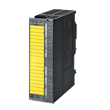
| Article number | 6ES7336-4GE00-0AB0 | |
| SM 336, f.AI 6 X 0/4 … 20mA HART | ||
| Supply voltage | ||
| Rated value (DC) | 24 V | |
| Reverse polarity protection | Yes | |
| Load voltage L+ | ||
| ● Rated value (DC) | 24 V | |
| ● Reverse polarity protection | Yes | |
| Input current | ||
| From power supply L+, typ. | 150 mA | |
| from backplane bus 5 V DC, max. | 90 mA | |
| Power loss | ||
| Power loss, typ. | 4.5 W | |
| Analog inputs | ||
| Number of analog inputs | 6 | |
| permissible input current for current input (destruction limit), max. | 40 mA | |
| Input ranges | ||
| ● Voltage | No | |
| ● Current | Yes | |
| ● Thermocouple | No | |
| ● Resistance thermometer | No | |
| ● Resistance | No | |
| Input ranges (rated values), currents | ||
| ● 0 to 20 mA | Yes | |
| — Input resistance (0 to 20 mA) | 150 Ω; typ. 150 ohms max. 175 ohms | |
| ● 4 mA to 20 mA | Yes | |
| — Input resistance (4 mA to 20 mA) | 150 Ω; typ. 150 ohms max. 175 ohms | |
| Cable length | ||
| ● shielded, max. | 1 000 m | |
| Analog value generation for the inputs | ||
| Integration and conversion time/resolution per channel | ||
| ● Resolution with overrange (bit including sign), max. | 16 bit; 15 bit + sign | |
| ● Integration time (ms) | 20 ms @ 50 Hz, 16.7 ms @ 60 Hz | |
| ● Interference voltage suppression for interference frequency f1 in Hz | f=n x (f1 ±0.5 %) | |
| Encoder | ||
| Connection of signal encoders | ||
| ● for current measurement as 2-wire transducer | Yes | |
| ● for current measurement as 4-wire transducer | Yes | |
| Errors/accuracies | ||
| Operational error limit in overall temperature range | ||
| ● Current, relative to input range, (+/-) | 0.2 %; 40 µA | |
| Basic error limit (operational limit at 25 °C) | ||
| ● Current, relative to input range, (+/-) | 0.1 % | |
| Interrupts/diagnostics/status information | ||
| Diagnostics function | Yes | |
| Alarms | ||
| ● Diagnostic alarm | Yes | |
| Diagnoses | ||
| ● Diagnostic information readable | Yes | |
| Diagnostics indication LED | ||
| ● Fail-safe operation | Yes | |
| ● Group error SF (red) | Yes | |
| ● Encoder supply Vs (green) | No | |
| Potential separation | ||
| Potential separation analog inputs | ||
| ● between the channels | Yes | |
| ● between the channels and backplane bus | Yes | |
| ● between the channels and the power supply of the electronics | Yes | |
| Isolation | ||
| Isolation tested with | 370V for 1 min | |
| Standards, approvals, certificates | ||
| Highest safety class achievable in safety mode | ||
| ● acc. to EN 954 | 4 | |
| ● Performance level according to ISO 13849-1 | e | |
| ● SIL acc. to IEC 61508 | SIL 3 | |
| connection method / header | ||
| required front connector | 20-pin | |
| Dimensions | ||
| Width | 40 mm | |
| Height | 125 mm | |
| Depth | 120 mm | |
| Weights | ||
| Weight, approx. | 350 g | |