USD 1,238.85 – USD 2,092.48Price range: USD 1,238.85 through USD 2,092.48
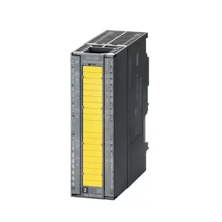
Fail-safe digital output modules are used centrally with SIMATIC S7-31xF-2 DP, and in the ET 200M distributed I/O device together with SIMATIC IM 151-7 F-CPU, S7-31xF-2 DP, S7-416F-2 and S7-400F/FH.The modules are, for example, suitable for connecting solenoid valves, DC contactors and indicator lights.
In the case of the SM 326 F-DO 10 x DC 24V/2A PP (6ES7 326-2BF10-0AB0), the function “Keep last valid value” can be used optionally in safety mode too. Together with the diagnostics capability of the module, this can be used for cost-optimized implementation of applications in, for example, the area of fire and gas alarm systems (in accordance with EN 54-2/-4 or NFPA72).
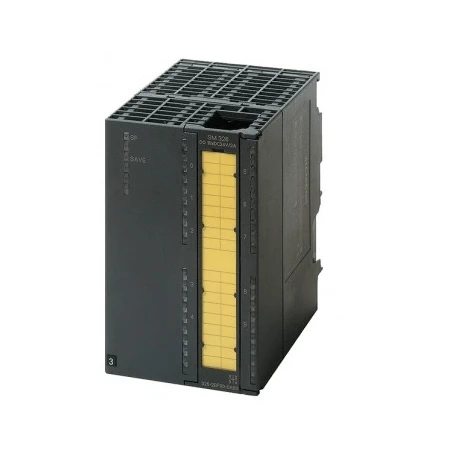
| Article number | 6ES7326-2BF10-0AB0 | 6ES7326-2BF41-0AB0 |
| SM326, F-DO10XDC24V/2A PP, failsafe | SM 326, F-DO 8 X DC 24V/2A PM | |
| Supply voltage | ||
| Rated value (DC) | 24 V; 1L+ | 24 V; 1L+ |
| Reverse polarity protection | Yes | Yes |
| Load voltage L+ | ||
| ● Rated value (DC) | 24 V; 2L+, 3L+ | 24 V; 2L+, 3L+ |
| ● Reverse polarity protection | No | No |
| Input current | ||
| from supply voltage 1L+, max. | 100 mA | 75 mA |
| from load voltage 2L+ (without load), max. | 100 mA | 100 mA |
| from load voltage 3L+ (without load), max. | 100 mA | 100 mA |
| from backplane bus 5 V DC, max. | 100 mA | 100 mA |
| Power loss | ||
| Power loss, typ. | 6 W | 12 W |
| Digital outputs | ||
| Number of digital outputs | 10 | 8 |
| Short-circuit protection | Yes | Yes |
| Limitation of inductive shutdown voltage to | L+ (-33 V) | |
| Switching capacity of the outputs | ||
| ● on lamp load, max. | 5 W | 5 W |
| Output voltage | ||
| ● for signal “1”, min. | L+ (-1.0 V) | L+ (-1.0 V) |
| Output current | ||
| ● for signal “1” rated value | 2 A | 2 A |
| ● for signal “1” permissible range for 0 to 40 °C, min. | 7 mA | 7 mA |
| ● for signal “1” permissible range for 0 to 40 °C, max. | 2.4 A | 2 A; 2 A for horizontal installation, 1 A for vertical installation |
| ● for signal “1” permissible range for 40 to 60 °C, min. | 7 mA | 7 mA |
| ● for signal “1” permissible range for 40 to 60 °C, max. | 2.4 A | 1 A; for horizontal installation |
| ● for signal “0” residual current, max. | 0.5 mA | 0.5 mA |
| Switching frequency | ||
| ● with resistive load, max. | 25 Hz | 30 Hz |
| ● with inductive load, max. | 25 Hz | 2 Hz |
| ● on lamp load, max. | 10 Hz | 10 Hz |
| Total current of the outputs (per group) | ||
| horizontal installation | ||
| — up to 40 °C, max. | 10 A | 7.5 A |
| — up to 60 °C, max. | 6 A | 5 A |
| vertical installation | ||
| — up to 40 °C, max. | 5 A | 5 A |
| Cable length | ||
| ● shielded, max. | 1 000 m | 200 m; 200 m for SIL 3, AK 6, Cat 4 |
| ● unshielded, max. | 600 m | 200 m |
| Interrupts/diagnostics/status information | ||
| Alarms | ||
| ● Diagnostic alarm | Yes | Yes; Parameterizable |
| Diagnoses | ||
| ● Diagnostic information readable | Yes | Yes |
| Diagnostics indication LED | ||
| ● Fail-safe operation | Yes | Yes |
| ● Group error SF (red) | Yes | Yes |
| Potential separation | ||
| Potential separation digital outputs | ||
| ● between the channels | Yes | Yes |
| ● between the channels, in groups of | 5 | 4 |
| ● between the channels and backplane bus | Yes | Yes |
| ● between the channels and the power supply of the electronics | Yes | Yes |
| Isolation | ||
| Isolation tested with | 370V for 1 min | 500 V DC/350 V AC |
| Standards, approvals, certificates | ||
| Highest safety class achievable in safety mode | ||
| ● acc. to DIN VDE 0801 | AK 5 and 6 | |
| ● acc. to EN 954 | Cat. 4 | Cat. 4 |
| ● Performance level according to ISO 13849-1 | e | e |
| ● SIL acc. to IEC 61508 | SIL 3 | SIL 3 |
| connection method / header | ||
| required front connector | 40-pin | 40-pin |
| Dimensions | ||
| Width | 40 mm | 80 mm |
| Height | 125 mm | 125 mm |
| Depth | 120 mm | 120 mm |
| Weights | ||
| Weight, approx. | 330 g | 465 g |