USD 213.84 – USD 1,448.20Price range: USD 213.84 through USD 1,448.20
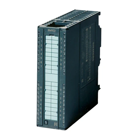
Digital input modules can be used to connect the PLC to digital process signals. They are suitable for connecting standard switches and two-wire proximity switches (BERO).
| Article number | 6ES7322-1BH01-0AA0 | 6ES7322-1BH10-0AA0 | 6ES7322-1BL00-0AA0 | 6ES7322-1BP00-0AA0 | 6ES7322-1BP50-0AA0 | 6ES7322-8BF00-0AB0 |
| SM322, 16DO 24V DC, 0,5A | SM322 High Speed, 16DO 24V DC, 0.5A | SM322, 32DO 24V DC, 0,5A | SM322 64DA, DC24V, 0,3A P-write | SM322 64DO, DC24V, 0.3A M-write | SM322, 8DO, 24V DC, 0,5A | |
| Supply voltage | ||||||
| Load voltage L+ | ||||||
| ● Rated value (DC) | 24 V | 24 V | 24 V | 24 V | 24 V | 24 V |
| ● permissible range, lower limit (DC) | 20.4 V | 20.4 V | 20.4 V | 20.4 V | 20.4 V | 20.4 V |
| ● permissible range, upper limit (DC) | 28.8 V | 28.8 V | 28.8 V | 28.8 V | 28.8 V | 28.8 V |
| Input current | ||||||
| from load voltage L+ (without load), max. | 80 mA | 110 mA | 160 mA | 75 mA | 75 mA | 90 mA |
| from backplane bus 5 V DC, max. | 80 mA | 70 mA | 110 mA | 100 mA | 100 mA | 70 mA |
| Power loss | ||||||
| Power loss, typ. | 4.9 W | 5 W | 6.6 W | 6 W | 6 W | 5 W |
| Digital outputs | ||||||
| Number of digital outputs | 16 | 16 | 32 | 64 | 64 | 8 |
| Short-circuit protection | Yes; Electronic | Yes; Electronic | Yes; Electronic | Yes; Electronic | Yes; Electronic | Yes; Electronic |
| ● Response threshold, typ. | 1 A | 1 A | 1 A | 0.7 to 1.9 A | 0.75 to 1.5 A | |
| Limitation of inductive shutdown voltage to | L+ (-53 V) | L+ (-53 V) | L+ (-53 V) | L+ (-53 V) | M+ (45 V) | L+ (-45 V) |
| Controlling a digital input | Yes | Yes | Yes | Yes | Yes | Yes |
| Switching capacity of the outputs | ||||||
| ● on lamp load, max. | 5 W | 5 W | 5 W | 5 W | 5 W | 5 W |
| Load resistance range | ||||||
| ● lower limit | 48 Ω | 48 Ω | 48 Ω | 80 Ω | 80 Ω | 48 Ω |
| ● upper limit | 4 kΩ | 4 kΩ | 4 kΩ | 10 kΩ | 10 kΩ | 3 kΩ |
| Output voltage | ||||||
| ● for signal “1”, min. | L+ (-0.8 V) | L+ (-0.8 V) | L+ (-0.8 V) | L+ (-0.5 V) | M+ (0.5 V) | L+ (-0.8 to -1.6 V) |
| Output current | ||||||
| ● for signal “1” rated value | 0.5 A | 0.5 A | 0.5 A | 0.3 A | 0.3 A | 0.5 A |
| ● for signal “1” permissible range, min. | 2.4 mA | 2.4 mA | ||||
| ● for signal “1” permissible range, max. | 0.36 A | 0.36 A | ||||
| ● for signal “1” permissible range for 0 to 40 °C, min. | 5 mA | 5 mA | 5 mA | 10 mA | ||
| ● for signal “1” permissible range for 0 to 40 °C, max. | 0.6 A | 0.6 A | 0.6 A | 0.6 A | ||
| ● for signal “1” permissible range for 40 to 60 °C, min. | 5 mA | 5 mA | 5 mA | 10 mA | ||
| ● for signal “1” permissible range for 40 to 60 °C, max. | 0.6 A | 0.6 A | 0.6 A | 0.6 A | ||
| ● for signal “1” minimum load current | 5 mA | 5 mA | 5 mA | 10 mA | ||
| ● for signal “0” residual current, max. | 0.5 mA | 0.5 mA | 0.5 mA | 0.1 mA | 0.5 mA | |
| Output delay with resistive load | ||||||
| ● “0” to “1”, max. | 100 µs | 100 µs | 100 µs | 550 µs | 450 µs | 180 µs |
| ● “1” to “0”, max. | 500 µs | 200 µs | 500 µs | 550 µs | 450 µs | 245 µs |
| Parallel switching of two outputs | ||||||
| ● for uprating | No | No | No | No | No | No |
| ● for redundant control of a load | Yes | Yes; only outputs of the same group | Yes; only outputs of the same group | Yes | Yes | Outputs with series diodes only |
| Switching frequency | ||||||
| ● with resistive load, max. | 100 Hz | 1 000 Hz | 100 Hz | 100 Hz | 100 Hz | 100 Hz |
| ● with inductive load, max. | 0.5 Hz | 0.5 Hz | 0.5 Hz | 0.5 Hz | 0.5 Hz | 2 Hz |
| ● with inductive load (acc. to IEC 60947-5-1, DC13), max. | 0.5 Hz | 0.5 Hz | 0.5 Hz | 2 Hz | ||
| ● on lamp load, max. | 10 Hz | 10 Hz | 10 Hz | 10 Hz | 10 Hz | 10 Hz |
| Total current of the outputs (per group) | ||||||
| horizontal installation | ||||||
| — up to 40 °C, max. | 4 A | 4 A | 4 A | 1.6 A | 1.6 A | 4 A |
| — up to 60 °C, max. | 3 A | 3 A | 3 A | 1.2 A | 1.2 A | 3 A |
| vertical installation | ||||||
| — up to 40 °C, max. | 2 A | 2 A | 2 A | 1.6 A | 1.6 A | 4 A |
| Cable length | ||||||
| ● shielded, max. | 1 000 m | 1 000 m | 1 000 m | 1 000 m | 1 000 m | 1 000 m |
| ● unshielded, max. | 600 m | 600 m | 600 m | 600 m | 600 m | 600 m |
| Interrupts/diagnostics/status information | ||||||
| Alarms | No | No | No | No | No | |
| Diagnostics function | No | No | No | No | No | Yes; Parameterizable |
| Alarms | ||||||
| ● Diagnostic alarm | No | No | No | No | No | Yes; Parameterizable |
| Diagnoses | ||||||
| ● Diagnostic information readable | No | No | No | Yes | ||
| ● Wire-break | No | No | No | No | No | Yes |
| ● Short-circuit | No | No | No | No | No | Yes |
| ● Fuse blown | No | No | No | No | No | |
| ● missing load voltage | No | No | No | No | No | Yes |
| Diagnostics indication LED | ||||||
| ● Rated load voltage PWR (green) | No | No | No | No | No | |
| ● Fuse OK FSG (green) | No | No | No | No | No | |
| ● Group error SF (red) | No | No | Yes | |||
| ● Status indicator digital output (green) | Yes | Yes; per channel | Yes; per channel | Yes | Yes; per channel | |
| ● Channel fault indicator F (red) | No | No | Yes | |||
| Potential separation | ||||||
| Potential separation digital outputs | ||||||
| ● between the channels | Yes | Yes | Yes | No | No | |
| ● between the channels, in groups of | 8 | 8 | 8 | 16 | 16 | 8 |
| ● between the channels and backplane bus | Yes; Optocoupler | Yes; Optocoupler | Yes; Optocoupler | Yes; Optocoupler | Yes; Optocoupler | Yes; Optocoupler |
| Isolation | ||||||
| Isolation tested with | 500 V DC | 500 V DC | 500 V DC | 500 V DC | 500 V DC | 500 V DC |
| connection method / header | ||||||
| required front connector | 20-pin | 20-pin | 40-pin | Cable: 6ES7392-4Bxx0-0AA0 terminal blocks: 6ES7392-1xN00-0AA0 | Cable: 6ES7392-4Bxx0-0AA0 terminal blocks: 6ES7392-1xN00-0AA0 | 20-pin |
| Dimensions | ||||||
| Width | 40 mm | 40 mm | 40 mm | 40 mm | 40 mm | 40 mm |
| Height | 125 mm | 125 mm | 125 mm | 125 mm | 125 mm | 125 mm |
| Depth | 120 mm | 120 mm | 120 mm | 112 mm | 112 mm | 120 mm |
| Weights | ||||||
| Weight, approx. | 190 g | 200 g | 260 g | 230 g | 230 g | 210 g |
| Article number | 6ES7322-5GH00-0AB0 | 6ES7322-1CF00-0AA0 | 6ES7322-1BF01-0AA0 | 6ES7322-1FF01-0AA0 | 6ES7322-5FF00-0AB0 | 6ES7322-1FH00-0AA0 |
| SM322, 16DO, AC/DC24-48V, 0,5A | SM322, 8DO, 48-125V DC, 1,5A | SM322, 8DO, 24V DC, 2A | SM322, 8DO, 120/230V AC, 1A | SM322, 8DO, AC120/230V, 2A | SM322, 16DO, 120/230V AC, 1A | |
| Supply voltage | ||||||
| Mains buffering | ||||||
| ● Mains/voltage failure stored energy time | 5 ms | |||||
| Load voltage L+ | ||||||
| ● Rated value (DC) | 24 V; 24 / 48 | 48 V; 48 V DC to 125 V DC | 24 V | |||
| ● permissible range, lower limit (DC) | 20.4 V | 40 V | 20.4 V | |||
| ● permissible range, upper limit (DC) | 57.6 V | 140 V | 28.8 V | |||
| ● Reverse polarity protection | Yes | Yes; through fuse | ||||
| Load voltage L1 | ||||||
| ● Rated value (AC) | 230 V; 120/230 V AC | 230 V; 120/230 V AC | 230 V; 120/230 V AC | |||
| ● permissible range, lower limit (AC) | 93 V | 79 V | 79 V | |||
| ● permissible range, upper limit (AC) | 264 V | 264 V | 264 V | |||
| ● permissible frequency range, lower limit | 47 Hz | |||||
| ● permissible frequency range, upper limit | 63 Hz | |||||
| Input current | ||||||
| from supply voltage L+, max. | 200 mA | |||||
| from load voltage L+ (without load), max. | 2 mA | 60 mA | ||||
| from load voltage L1 (without load), max. | 2 mA | 2 mA | 2 mA | |||
| from backplane bus 5 V DC, max. | 100 mA | 100 mA | 40 mA | 100 mA | 100 mA | 200 mA |
| Power loss | ||||||
| Power loss, typ. | 2.8 W | 7.2 W | 6.8 W | 8.6 W | 8.6 W | 8.6 W |
| Digital outputs | ||||||
| Number of digital outputs | 16 | 8 | 8 | 8 | 8 | 16 |
| Short-circuit protection | No; to be provided externally | Yes; Electronic | Yes; Electronic | Yes; Fuse 8 A, 250 V; per group | Yes; to be provided externally; fuse 3.15 A / 250 V, quick response | Yes; Fuse 8 A, 250 V; per group |
| ● Response threshold, typ. | 4.4 A | 3 A | ||||
| ● required current for fuse shutdown, min. | 40 A | 40 A | ||||
| ● Response time, max. | 300 ms | 300 ms | ||||
| Limitation of inductive shutdown voltage to | M (-1 V) | L+ (-48 V) | ||||
| Controlling a digital input | Yes | Yes | Yes | Yes | Yes | Yes |
| Size of motor starters according to NEMA, max. | Size 5 according to NEMA | 5 NEMA compliant | Size 5 according to NEMA | 4 NEMA compliant | ||
| Spare fuses | 6.3 A / 250 V, quick-response, 5x 20 mm | 8 A / quick response | 8 A / quick response | |||
| Zero-crossing switch | Yes; Max. 60 V | Yes; 60 V | ||||
| Switching capacity of the outputs | ||||||
| ● on lamp load, max. | 2.5 W | 15 W; 15 W (48 V) or 40 W (125 V) | 10 W | 50 W | 50 W | 50 W |
| Load resistance range | ||||||
| ● lower limit | 12 Ω | |||||
| ● upper limit | 4 kΩ | |||||
| Output voltage | ||||||
| ● for signal “1”, min. | L+ (-0.25 V) | L+ (-1.2 V) | L+ (-0.8 V) | L1 (-1.5 V) | L1 (-8.5 V) | |
| ● for signal “1” (at max. current), min. | L1 (-1.5 V) | L1 (-1.5 V) | ||||
| ● for signal “1” (at min. current), min. | L1 (-8.5 V) | L1 (-8.5 V) | ||||
| Output current | ||||||
| ● for signal “1” rated value | 0.5 A | 1.5 A | 2 A | 2 A | 2 A | 1 A |
| ● for signal “1” permissible range for 0 to 40 °C, min. | 10 mA | 5 mA | 10 mA | 10 mA | 10 mA | |
| ● for signal “1” permissible range for 0 to 40 °C, max. | 0.5 A | 1.5 A | 2.4 A | 2 A | 2 A | 1 A |
| ● for signal “1” permissible range for 40 to 60 °C, min. | 10 mA | 5 mA | 10 mA | 10 mA | 10 mA | |
| ● for signal “1” permissible range for 40 to 60 °C, max. | 0.5 A | 1.5 A | 2.4 A | 1 A | 1 A | 0.5 A |
| ● for signal “1” minimum load current | 10 mA | 5 mA | 10 mA | 10 mA | 10 mA | |
| ● for signal “1” permissible surge current, max. | 1.5 A; for 50 ms, 1 A 2 s one-time | 3 A; for 10 ms | 20 A; max. 1 AC cycle | 20 A; with 2 half waves | 20 A; with 2 half waves | |
| ● for signal “0” residual current, max. | 10 µA | 0.5 mA | 0.5 mA | 2 mA | 2 mA | 2 mA |
| Output delay with resistive load | ||||||
| ● “0” to “1”, max. | 6 ms | 2 ms | 100 µs | 1 AC cycle | ||
| ● “1” to “0”, max. | 3 ms | 15 ms | 500 µs | 1 AC cycle | ||
| Parallel switching of two outputs | ||||||
| ● for uprating | No | No | No | No | No | No |
| ● for redundant control of a load | Yes | Yes; only outputs of the same group | Yes | Yes | Yes | Yes; only outputs of the same group |
| Switching frequency | ||||||
| ● with resistive load, max. | 10 Hz | 25 Hz | 100 Hz | 10 Hz | 10 Hz | 10 Hz |
| ● with inductive load, max. | 0.5 Hz | 0.5 Hz | 0.5 Hz | 0.5 Hz | 0.5 Hz | 0.5 Hz |
| ● with inductive load (acc. to IEC 60947-5-1, DC13), max. | 0.5 Hz | 0.5 Hz | 0.5 Hz | |||
| ● with inductive load (acc. to IEC 60947-5-1, AC15), max. | 0.5 Hz | 0.5 Hz | 0.5 Hz | |||
| ● on lamp load, max. | 0.5 Hz | 10 Hz | 10 Hz | 1 Hz | 1 Hz | 1 Hz |
| Total current of the outputs (per group) | ||||||
| horizontal installation | ||||||
| — up to 40 °C, max. | 0.5 A; 8 A per module | 6 A | 4 A | 4 A | 8 A | 4 A |
| — up to 50 °C, max. | 4 A | |||||
| — up to 60 °C, max. | 0.5 A; 8 A per module | 3 A | 4 A | 2 A | 4 A | 2 A |
| vertical installation | ||||||
| — up to 40 °C, max. | 0.5 A; 8 A per module | 4 A | 4 A | 2 A | 4 A | 2 A |
| Cable length | ||||||
| ● shielded, max. | 1 000 m | 1 000 m | 1 000 m | 1 000 m | 1 000 m | 1 000 m |
| ● unshielded, max. | 600 m | 600 m | 600 m | 600 m | 600 m | 600 m |
| Interrupts/diagnostics/status information | ||||||
| Alarms | No | No | No | |||
| Diagnostics function | Yes; Parameterizable | No | No | Yes; Fuse blown or load voltage missing | Yes; Parameterizable | Yes; Fuse blown or load voltage missing |
| Alarms | ||||||
| ● Diagnostic alarm | Yes; Parameterizable | No | No | No | Yes; Parameterizable | No |
| Diagnoses | ||||||
| ● Diagnostic information readable | Yes | |||||
| ● Wire-break | No | No | No | No | ||
| ● Short-circuit | No | No | No | No | ||
| ● Fuse blown | No | No | Yes | Yes | ||
| ● missing load voltage | No | No | Yes | No | ||
| Diagnostics indication LED | ||||||
| ● Rated load voltage PWR (green) | No | No | Yes | No | ||
| ● Fuse OK FSG (green) | No | No | Yes | Yes; Red LED for fuse | ||
| ● Group error SF (red) | Yes | Yes | Yes | Yes | Yes | |
| ● Status indicator digital output (green) | Yes | Yes | Yes; per channel | Yes | Yes | Yes |
| Potential separation | ||||||
| Potential separation digital outputs | ||||||
| ● between the channels | Yes | Yes | Yes | Yes | Yes | |
| ● between the channels, in groups of | 1 | 4 | 4 | 4 | 1 | 8 |
| ● between the channels and backplane bus | Yes; Optocoupler | Yes; Optocoupler | Yes; Optocoupler | Yes; Optocoupler | Yes; Optocoupler | Yes; Optocoupler |
| ● between the channels and the power supply of the electronics | Yes | |||||
| Isolation | ||||||
| Isolation tested with | 1 500 V AC | 1 500 V AC | 500 V DC | 1 500 V AC | 1 500 V AC | 4 000 V DC |
| connection method / header | ||||||
| required front connector | 40-pin | 20-pin | 20-pin | 20-pin | 40-pin | 20-pin |
| Dimensions | ||||||
| Width | 40 mm | 40 mm | 40 mm | 40 mm | 40 mm | 40 mm |
| Height | 125 mm | 125 mm | 125 mm | 125 mm | 125 mm | 125 mm |
| Depth | 120 mm | 120 mm | 120 mm | 120 mm | 120 mm | 120 mm |
| Weights | ||||||
| Weight, approx. | 260 g | 250 g | 190 g | 275 g | 275 g | 275 g |
| Article number | 6ES7322-1FL00-0AA0 | 6ES7322-1HF01-0AA0 | 6ES7322-1HF10-0AA0 | 6ES7322-5HF00-0AB0 | 6ES7322-1HH01-0AA0 |
| SM322, 32DO, 120/230V AC, 1A | SM322, 8DA, 24V DC/2A or 230V AC/2A | SM322, 8DA, 24V DC/5A OR 230V AC/5A | SM322, 8DO Relay, 24VDC, 120-230V AC, 5A | SM322, 16DO Relay | |
| Supply voltage | |||||
| Load voltage L+ | |||||
| ● Rated value (DC) | 24 V | 120 V | 24 V | 120 V | |
| ● permissible range, lower limit (DC) | 24 V | ||||
| ● permissible range, upper limit (DC) | 120 V | ||||
| Load voltage L1 | |||||
| ● Rated value (AC) | 120 V; 120/230 V AC | 230 V | 230 V | 230 V | |
| ● permissible range, lower limit (AC) | 79 V | ||||
| ● permissible range, upper limit (AC) | 264 V | ||||
| ● permissible frequency range, lower limit | 47 Hz | ||||
| ● permissible frequency range, upper limit | 63 Hz | ||||
| Input current | |||||
| from supply voltage L+, max. | 160 mA | 125 mA | 160 mA | 250 mA | |
| from load voltage L1 (without load), max. | 10 mA | ||||
| from backplane bus 5 V DC, max. | 190 mA | 40 mA | 40 mA | 100 mA | 100 mA |
| Power loss | |||||
| Power loss, typ. | 25 W | 3.2 W | 3.2 W | 3.5 W | 4.5 W |
| Digital outputs | |||||
| Number of digital outputs | 32 | 8; Relays | 8; Relays | 8; Relays | 16; Relays |
| Short-circuit protection | No | No | No; to be provided externally | No; to be provided externally | No |
| Controlling a digital input | Yes | Yes | Yes | Yes | Yes |
| Size of motor starters according to NEMA, max. | Size 4 according to NEMA | Size 5 according to NEMA | |||
| Zero-crossing switch | Yes; Max. 60 V | ||||
| Switching capacity of the outputs | |||||
| ● on lamp load, max. | 50 W | 50 W | 1 500 W; 230 V AC | 1 500 W; 230 V AC | 50 W; 230 V AC |
| ● Low energy/fluorescent lamps with electronic control gear | 10x 58 W | 10x 58 W | 10x 58 W | ||
| ● Fluorescent tubes, conventionally compensated | 1x 58 W | 1x 58 W | 1x 58 W | ||
| ● Fluorescent tubes, uncompensated | 10x 58 W | 10x 58 W | 10x 58 W | ||
| Output voltage | |||||
| ● for signal “1”, min. | L1 (-0.8 V) | ||||
| Output current | |||||
| ● for signal “1” rated value | 1 A | 2 A | 5 A | 5 A | 2 A |
| ● for signal “1” permissible range for 0 to 40 °C, min. | 10 mA | ||||
| ● for signal “1” permissible range for 0 to 40 °C, max. | 1 A | ||||
| ● for signal “1” permissible range for 40 to 60 °C, min. | 10 mA | ||||
| ● for signal “1” permissible range for 40 to 60 °C, max. | 1 A | ||||
| ● for signal “1” minimum load current | 10 mA | 5 mA | 5 mA | 10 mA | 10 mA |
| ● for signal “1” permissible surge current, max. | 10 A; per group (for 2 AC cycles) | ||||
| ● for signal “0” residual current, max. | 2 mA | ||||
| Output delay with resistive load | |||||
| ● “0” to “1”, max. | 1 AC cycle | ||||
| ● “1” to “0”, max. | 1 AC cycle | ||||
| Parallel switching of two outputs | |||||
| ● for uprating | No | No | No | No | No |
| ● for redundant control of a load | Yes; only outputs of the same group | Yes | Yes | Yes | Yes |
| Switching frequency | |||||
| ● with resistive load, max. | 10 Hz | 2 Hz | 2 Hz | 2 Hz | 1 Hz |
| ● with inductive load, max. | 0.5 Hz | 0.5 Hz | 0.5 Hz | 0.5 Hz | 0.5 Hz |
| ● with inductive load (acc. to IEC 60947-5-1, AC15), max. | 0.5 Hz | ||||
| ● With inductive load (to IEC 60947-5-1, DC13/AC15), max. | 0.5 Hz | 0.5 Hz | 0.5 Hz | 0.5 Hz | |
| ● on lamp load, max. | 1 Hz | 2 Hz | 2 Hz | 2 Hz | 1 Hz |
| ● mechanical, max. | 10 Hz | 10 Hz | 10 Hz | 10 Hz | |
| Total current of the outputs (per group) | |||||
| horizontal installation | |||||
| — up to 40 °C, max. | 4 A | ||||
| — up to 60 °C, max. | 3 A | 5 A | 5 A | 8 A | |
| vertical installation | |||||
| — up to 40 °C, max. | 4 A | 5 A | 5 A | 8 A | |
| Relay outputs | |||||
| ● Rated supply voltage of relay coil L+ (DC) | 24 V; 110 mA | 24 V | 24 V | ||
| ● Contact connection (internal) | Yes; SIOV-CU4032 K275G | No | Yes; 330 Ohm, 0.1uF | No | |
| ● Number of operating cycles, max. | 300 000; 230 V AC: 100 000; 120 V AC: 200 000; 24 V DC: 300 000 (at 2 A) | 300 000; 300 000 (24 V DC, at 2 A); 200 000 (120 V AC, at 3 A); 100 000 (230 V AC, at 3 A) | 100 000; 100 000 (24 V DC, at 5 A), 100 000 (230 V AC, at 5 A) | 100 000; 50 000 (24 V DC, at 2 A); 700 000 (120 V AC, at 2 A); 100 000 (230 V AC, at 2 A) | |
| Switching capacity of contacts | |||||
| — with inductive load, max. | 2 A; 2 A (230 V AC), 2 A (24 V DC) | 3 A; 3 A (230 V DC), 2 A (24 V AC) | 5 A; 5 A (230 V DC), 5 A (24 V AC) | 2 A; 2 A (230 V AC), 2 A (24 V DC) | |
| — with resistive load, max. | 2 A | 8 A; 8 A (230 V DC), 5 A (24 V AC) | 5 A; 5 A (230 V DC), 5 A (24 V AC) | 2 A; 2 A (230 V AC), 2 A (24 V DC) | |
| — Thermal continuous current, max. | 3 A | 8 A | 5 A | 2 A | |
| Cable length | |||||
| ● shielded, max. | 1 000 m | 1 000 m | 1 000 m | 1 000 m | 1 000 m |
| ● unshielded, max. | 600 m | 600 m | 600 m | 600 m | 600 m |
| Interrupts/diagnostics/status information | |||||
| Alarms | No | No | No | Yes | No |
| Diagnostics function | Yes; Fuse blown or load voltage missing | No | No | Yes; Parameterizable | No |
| Alarms | |||||
| ● Diagnostic alarm | No | No | No | Yes; Parameterizable | No |
| Diagnoses | |||||
| ● Diagnostic information readable | Yes | ||||
| ● Wire-break | No | No | No | ||
| ● Short-circuit | No | No | No | ||
| ● Fuse blown | No | No | No | ||
| ● missing load voltage | No | No | No | ||
| Diagnostics indication LED | |||||
| ● Rated load voltage PWR (green) | No | No | No | ||
| ● Fuse OK FSG (green) | No | No | No | ||
| ● Group error SF (red) | Yes | Yes | |||
| ● Status indicator digital output (green) | Yes; per channel | Yes | Yes | Yes | Yes |
| Potential separation | |||||
| Potential separation digital outputs | |||||
| ● between the channels | Yes | Yes | Yes | Yes | Yes |
| ● between the channels, in groups of | 8 | 2 | 1 | 1 | 8 |
| ● between the channels and backplane bus | Yes; Optocoupler | Yes; Optocoupler | Yes; Optocoupler | Yes; Optocoupler | Yes; Optocoupler |
| ● Between the channels and the power supply of the relays | Yes | ||||
| Isolation | |||||
| Isolation tested with | 4 000 V DC | 1 500 V AC | 2 000 V AC | 1 500 V AC | 1 500 V AC |
| connection method / header | |||||
| required front connector | 20-pin | 20-pin | 40-pin | 40-pin | 20-pin |
| Dimensions | |||||
| Width | 80 mm | 40 mm | 40 mm | 40 mm | 40 mm |
| Height | 125 mm | 125 mm | 125 mm | 125 mm | 125 mm |
| Depth | 117 mm | 120 mm | 120 mm | 120 mm | 120 mm |
| Weights | |||||
| Weight, approx. | 500 g | 190 g | 320 g | 320 g | 250 g |