USD 162.59 – USD 1,177.80Price range: USD 162.59 through USD 1,177.80
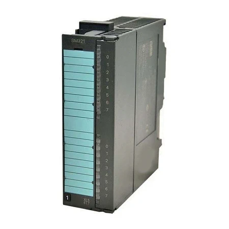
Digital input modules can be used to connect the PLC to digital process signals. They are suitable for connecting standard switches and two-wire proximity switches (BERO).
| Article number | 6ES7321-1BH02-0AA0 | 6ES7321-1BH50-0AA0 | 6ES7321-1BL00-0AA0 | 6ES7321-1BP00-0AA0 | 6ES7321-1BH10-0AA0 |
| SM321, 16DI, DC24V | SM321, 16DI, DC24V, Source Input | SM321, 32DI, DC24V | SM321, 64 DI, DC 24V, 3MS, P/M reading | SM321,16DI,DC24V, 0.05ms Input Delay. | |
| Supply voltage | |||||
| Load voltage L+ | |||||
| ● Rated value (DC) | 24 V | 24 V | 24 V | 24 V | 24 V |
| ● permissible range, lower limit (DC) | 20.4 V | 20.4 V | 20.4 V | 20.4 V | |
| ● permissible range, upper limit (DC) | 28.8 V | 28.8 V | 28.8 V | 28.8 V | |
| ● Reverse polarity protection | Yes | ||||
| Input current | |||||
| from backplane bus 5 V DC, max. | 10 mA | 10 mA | 15 mA | 100 mA | 110 mA |
| Power loss | |||||
| Power loss, typ. | 3.5 W | 3.5 W | 6.5 W | 7 W | 3.8 W |
| Digital inputs | |||||
| Number of digital inputs | 16 | 16 | 32 | 64 | 16 |
| Input characteristic curve in accordance with IEC 61131, type 1 | Yes | Yes | Yes | Yes | Yes |
| Number of simultaneously controllable inputs | |||||
| all mounting positions | |||||
| — up to 40 °C, max. | 64 | ||||
| — up to 60 °C, max. | 32 | ||||
| horizontal installation | |||||
| — up to 40 °C, max. | 16 | 16 | 32 | 64 | 16 |
| — up to 60 °C, max. | 16 | 16 | 16 | 32 | 16 |
| vertical installation | |||||
| — up to 40 °C, max. | 16 | 16 | 32 | 32 | 16 |
| Input voltage | |||||
| ● Type of input voltage | DC | DC | DC | DC | DC |
| ● Rated value (DC) | 24 V | 24 V | 24 V | 24 V | 24 V |
| ● for signal “0” | -30 to +5 V | -5 to +30V | -30 to +5 V | -30 to +5 V | -30 to +5 V |
| ● for signal “1” | 13 to 30V | -13 to -30V | 13 to 30V | 13 to 30V | 13 to 30V |
| Input current | |||||
| ● for signal “1”, typ. | 7 mA | 7 mA | 7 mA | 4.2 mA | 7 mA |
| Input delay (for rated value of input voltage) | |||||
| for standard inputs | |||||
| — parameterizable | No | No | No | No | No |
| — Rated value | 4.2 ms | ||||
| — at “0” to “1”, min. | 1.2 ms | 1.2 ms | 1.2 ms | 1.2 ms | 25 µs |
| — at “0” to “1”, max. | 4.8 ms | 4.8 ms | 4.8 ms | 4.8 ms | 75 µs |
| — at “1” to “0”, min. | 1.2 ms | 1.2 ms | 1.2 ms | 1.2 ms | 25 µs |
| — at “1” to “0”, max. | 4.8 ms | 4.8 ms | 4.8 ms | 4.8 ms | 75 µs |
| Cable length | |||||
| ● shielded, max. | 1 000 m | 1 000 m | 1 000 m | 1 000 m | 1 000 m |
| ● unshielded, max. | 600 m | 600 m | 600 m | 600 m | 600 m |
| Encoder | |||||
| Connectable encoders | |||||
| ● 2-wire sensor | Yes | Yes | Yes | No | Yes |
| — permissible quiescent current (2-wire sensor), max. | 1.5 mA | 1.5 mA | 1.5 mA | 1.5 mA | |
| Interrupts/diagnostics/status information | |||||
| Alarms | No | No | No | No | No |
| Diagnostics function | No | No | No | No | No |
| Alarms | |||||
| ● Diagnostic alarm | No | No | No | No | No |
| ● Hardware interrupt | No | No | No | No | No |
| Diagnoses | |||||
| ● Diagnostic information readable | No | ||||
| ● Wire-break | No | ||||
| Diagnostics indication LED | |||||
| ● Group error SF (red) | No | ||||
| ● Status indicator digital input (green) | Yes | Yes | Yes | Yes | Yes |
| ● Encoder supply Vs (green) | No | ||||
| Potential separation | |||||
| Potential separation digital inputs | |||||
| ● between the channels | No | No | No | No | No |
| ● between the channels, in groups of | 16 | 16 | 16 | 16 | 16 |
| ● between the channels and backplane bus | Yes; Optocoupler | Yes; Optocoupler | Yes; Optocoupler | Yes; Optocoupler | Yes; Optocoupler |
| Isolation | |||||
| Isolation tested with | 500 V DC | 500 V DC | 500 V DC | 500 V DC | 500 V DC |
| connection method / header | |||||
| required front connector | 20-pin | 20-pin | 40-pin | Cable: 6ES7392-4Bxx0-0AA0 terminal blocks: 6ES7392-1xN00-0AA0 | 20-pin |
| Dimensions | |||||
| Width | 40 mm | 40 mm | 40 mm | 40 mm | 40 mm |
| Height | 125 mm | 125 mm | 125 mm | 125 mm | 125 mm |
| Depth | 120 mm | 120 mm | 120 mm | 112 mm | 120 mm |
| Weights | |||||
| Weight, approx. | 200 g | 200 g | 260 g | 230 g | 200 g |
| Article number | 6ES7321-7BH01-0AB0 | 6ES7321-1CH00-0AA0 | 6ES7321-1CH20-0AA0 | 6ES7321-1FH00-0AA0 |
| SM321, 16DI, 24V DC | SM321, 16 DI, AC/DC 24-48V, 1ch/common | SM321, 16DI, DC48-125V | SM321, 16 DI, 120/230V AC | |
| Supply voltage | ||||
| Load voltage L+ | ||||
| ● Rated value (DC) | 24 V | 24 V | 48 V | |
| ● permissible range, lower limit (DC) | 20.4 V | 24 V | 48 V | |
| ● permissible range, upper limit (DC) | 28.8 V | 48 V | 125 V | |
| ● Reverse polarity protection | Yes | |||
| Load voltage L1 | ||||
| ● Rated value (AC) | 24 V | 230 V; 120/230 V AC; all load voltages must have the same phase. | ||
| ● permissible range, lower limit (AC) | 24 V | |||
| ● permissible range, upper limit (AC) | 48 V | |||
| Input current | ||||
| from load voltage L+ (without load), max. | 90 mA | |||
| from backplane bus 5 V DC, max. | 130 mA | 100 mA | 40 mA | 29 mA |
| Encoder supply | ||||
| Number of outputs | 2 | |||
| Type of output voltage | L+ (-2.5 V) | |||
| Short-circuit protection | Yes; Electronic | |||
| additional (redundant) feed | Yes | |||
| Output current | ||||
| ● Rated value | 120 mA | |||
| ● permissible range, lower limit | 0 mA | |||
| ● permissible range, upper limit | 150 mA | |||
| Power loss | ||||
| Power loss, typ. | 4 W | 1.5 W; at 24 V; 2,8 W at 48 V | 4.3 W | 4.9 W |
| Digital inputs | ||||
| Number of digital inputs | 16 | 16 | 16 | 16 |
| Input characteristic curve in accordance with IEC 61131, type 1 | Yes | Yes | Yes | |
| Input characteristic curve in accordance with IEC 61131, type 2 | Yes | |||
| Number of simultaneously controllable inputs | ||||
| horizontal installation | ||||
| — up to 40 °C, max. | 16 | 16 | 8 | 16 |
| — up to 60 °C, max. | 16 | 16 | 8; 6 to Ue 146 V | 16 |
| vertical installation | ||||
| — up to 40 °C, max. | 16 | 16 | 8 | 16 |
| Input voltage | ||||
| ● Type of input voltage | DC | AC/DC | DC | AC |
| ● Rated value (DC) | 24 V | 24 V; DC 24 or 48 V | 48 V; 48 V DC to 125 V DC | |
| ● Rated value (AC) | 24 V; 24 V AC or 48 V AC (0 … 63 Hz) | 230 V; 120/230 V AC (47 … 63 Hz) | ||
| ● for signal “0” | -30 to +5 V | -5V AC to +5V AC | -146 V DC to +15 V DC | 0 to 40V |
| ● for signal “1” | 13 to 30V | 14V AC to 60V AC | 30 V DC to 146 V DC | 79 to 264V |
| Input current | ||||
| ● for signal “0”, min. | -1 mA | |||
| ● for signal “0”, max. (permissible quiescent current) | 1 mA | |||
| ● for signal “1”, typ. | 7 mA | 2.7 mA | 3.5 mA | 6.5 mA; (120 V, 60 Hz), 16 mA (230 V, 50 Hz) |
| Input delay (for rated value of input voltage) | ||||
| for standard inputs | ||||
| — parameterizable | Yes; 0.1 / 0.5 / 3 / 15 / 20 ms | No | No | No |
| — at “0” to “1”, min. | 16 ms | 0.1 ms | 25 ms | |
| — at “0” to “1”, max. | 16 ms | 3.5 ms | 25 ms | |
| — at “1” to “0”, min. | 0.7 ms | |||
| — at “1” to “0”, max. | 16 ms | 3 ms | 25 ms | |
| Encoder connection | ||||
| ● Fixed current limitation for wire-break monitoring, min. | 10 kΩ | |||
| ● Fixed current limitation for wire-break monitoring, max. | 18 kΩ | |||
| Cable length | ||||
| ● shielded, max. | 1 000 m | 1 000 m | 1 000 m | 1 000 m |
| ● unshielded, max. | 600 m | 600 m | 600 m | 600 m |
| Encoder | ||||
| Connectable encoders | ||||
| ● 2-wire sensor | Yes | Yes | Yes | Yes |
| — permissible quiescent current (2-wire sensor), max. | 2 mA | 1 mA | 1 mA | 2 mA |
| Interrupts/diagnostics/status information | ||||
| Alarms | Yes | No | No | No |
| Diagnostics function | Yes; Parameterizable | No | No | No |
| Alarms | ||||
| ● Diagnostic alarm | Yes; Parameterizable | No | No | No |
| ● Hardware interrupt | Yes; Parameterizable | No | No | No |
| Diagnoses | ||||
| ● Diagnostic information readable | Yes | |||
| ● Wire-break | Yes; to I< 1 mA | |||
| Diagnostics indication LED | ||||
| ● Group error SF (red) | Yes | No | No | No |
| ● Status indicator digital input (green) | Yes | Yes | Yes | Yes |
| ● Encoder supply Vs (green) | Yes | |||
| Potential separation | ||||
| Potential separation digital inputs | ||||
| ● between the channels | No | Yes | No | No |
| ● between the channels, in groups of | 16 | 1 | 8 | 4 |
| ● between the channels and backplane bus | Yes; Optocoupler | Yes; Optocoupler | Yes; Optocoupler | Yes; Optocoupler |
| Isolation | ||||
| Isolation tested with | 500 V DC | 1 500 V AC | 1 500 V DC | 4 000 V DC |
| connection method / header | ||||
| required front connector | 20-pin | 40-pin | 20-pin | 20-pin |
| Dimensions | ||||
| Width | 40 mm | 40 mm | 40 mm | 40 mm |
| Height | 125 mm | 125 mm | 125 mm | 125 mm |
| Depth | 120 mm | 120 mm | 120 mm | 120 mm |
| Weights | ||||
| Weight, approx. | 200 g | 260 g | 200 g | 240 g |
| Article number | 6ES7321-1EL00-0AA0 | 6ES7321-1FF01-0AA0 | 6ES7321-1FF10-0AA0 |
| SM321, 32DI, AC120V | SM321, 8DI, AC120/230V | SM321, 8 DI, AC/DC 120/230V, 1ch/common | |
| Supply voltage | |||
| Load voltage L1 | |||
| ● Rated value (AC) | 120 V | 230 V; 120/230 V AC | 230 V; 120/230 V AC; all load voltages must have the same phase. |
| Input current | |||
| from backplane bus 5 V DC, max. | 16 mA | 29 mA | 100 mA |
| Power loss | |||
| Power loss, typ. | 4 W | 4.9 W | 4.9 W |
| Digital inputs | |||
| Number of digital inputs | 32 | 8 | 8 |
| Input characteristic curve in accordance with IEC 61131, type 1 | Yes | Yes | |
| Input characteristic curve in accordance with IEC 61131, type 2 | Yes | ||
| Number of simultaneously controllable inputs | |||
| horizontal installation | |||
| — up to 40 °C, max. | 32 | ||
| — up to 60 °C, max. | 24 | 8 | 8 |
| vertical installation | |||
| — up to 40 °C, max. | 32 | 8 | 8 |
| Input voltage | |||
| ● Type of input voltage | AC | AC | AC |
| ● Rated value (AC) | 120 V; 47 … 63 Hz | 230 V; 120/230 V AC (47 … 63 Hz) | 120 V; 120/230 V AC (47 … 63 Hz) |
| ● for signal “0” | 0 to 20V | 0 to 40V | 0 to 40V |
| ● for signal “1” | 74 to 132V | 79 to 264V | 79 to 264V |
| Input current | |||
| ● for signal “1”, typ. | 21 mA | 6.5 mA; (120 V); 11 mA (230 V) | 7.5 mA; (120 V); 17.3 mA (230 V) |
| Input delay (for rated value of input voltage) | |||
| for standard inputs | |||
| — parameterizable | No | No | No |
| — at “0” to “1”, max. | 15 ms | 25 ms | 25 ms |
| — at “1” to “0”, max. | 25 ms | 25 ms | 25 ms |
| Cable length | |||
| ● shielded, max. | 1 000 m | 1 000 m | 1 000 m |
| ● unshielded, max. | 600 m | 600 m | 600 m |
| Encoder | |||
| Connectable encoders | |||
| ● 2-wire sensor | Yes | Yes | Yes |
| — permissible quiescent current (2-wire sensor), max. | 4 mA | 2 mA | 2 mA |
| Interrupts/diagnostics/status information | |||
| Alarms | No | No | No |
| Diagnostics function | No | No | No |
| Alarms | |||
| ● Diagnostic alarm | No | No | No |
| ● Hardware interrupt | No | No | No |
| Diagnostics indication LED | |||
| ● Group error SF (red) | No | No | No |
| ● Status indicator digital input (green) | Yes; per channel | Yes | Yes |
| Potential separation | |||
| Potential separation digital inputs | |||
| ● between the channels | No | No | Yes |
| ● between the channels, in groups of | 8 | 2 | 1 |
| ● between the channels and backplane bus | Yes; Optocoupler | Yes; Optocoupler | Yes; Optocoupler |
| Isolation | |||
| Isolation tested with | 2 500 V DC | 4 000 V DC | 1 500 V AC |
| connection method / header | |||
| required front connector | 40-pin | 20-pin | 40-pin |
| Dimensions | |||
| Width | 40 mm | 40 mm | 40 mm |
| Height | 125 mm | 125 mm | 125 mm |
| Depth | 120 mm | 120 mm | 120 mm |
| Weights | |||
| Weight, approx. | 300 g | 240 g | 240 g |