USD 1,033.85
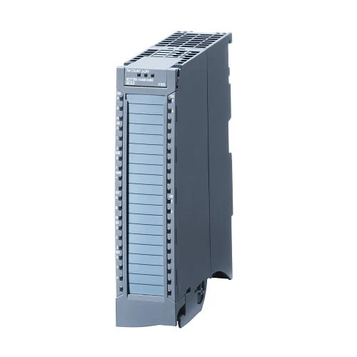
The position detection module TMPosInput 2 is used for counting tasks as well as position detection.
In counting mode, the module detects high-speed signals with high frequencies and forwards the counter reading and the current speed to the control. The counter control ensures a precise counter result and rapid response in the system via digital input and output signals. Comprehensive parameterization options provide optimum adaptation to the task at hand and reduce control load.
For position detection, incremental encoders or SSI absolute encoders can be connected. Absolute encoders offer the advantage that the position of the axis is immediately available after switching on without the need for a reference run.
| Article number | 6ES7551-1AB00-0AB0 | |
| S7-1500, TM Posinput 2 | ||
| General information | ||
| Product type designation | TM PosInput 2 | |
| Firmware version | V1.3 | |
| ● FW update possible | Yes | |
| Product function | ||
| ● I&M data | Yes; I&M0 to I&M3 | |
| ● Isochronous mode | Yes | |
| Engineering with | ||
| ● STEP 7 TIA Portal configurable/integrated from version | V12 (FW V1.0) … V15 (FW V1.3)/V12 (FW V1.0), V13 (FW V1.1) | |
| ● PROFIBUS from GSD version/GSD revision | GSD Revision 5 | |
| ● PROFINET from GSD version/GSD revision | V2.3 / – | |
| Installation type/mounting | ||
| Rail mounting | Yes; S7-1500 mounting rail | |
| Supply voltage | ||
| Load voltage L+ | ||
| ● Rated value (DC) | 24 V | |
| ● permissible range, lower limit (DC) | 19.2 V | |
| ● permissible range, upper limit (DC) | 28.8 V | |
| ● Reverse polarity protection | Yes | |
| Input current | ||
| Current consumption, max. | 75 mA; without load | |
| Encoder supply | ||
| Number of outputs | 4; One 5V and 24V encoder supply per channel | |
| 5 V encoder supply | ||
| ● 5 V | Yes; 5.2 V ±2 % | |
| ● Short-circuit protection | Yes | |
| ● Output current, max. | 300 mA; Per channel | |
| 24 V encoder supply | ||
| ● 24 V | Yes; L+ (-0.8 V) | |
| ● Short-circuit protection | Yes | |
| ● Output current, max. | 300 mA; Per channel | |
| Power | ||
| Power available from the backplane bus | 1.3 W | |
| Power loss | ||
| Power loss, typ. | 5.5 W | |
| Address area | ||
| Address space per module | ||
| ● Inputs | 16 byte; Per channel | |
| ● Outputs | 12 byte; per channel; 4 bytes for Motion Control | |
| Digital inputs | ||
| Number of digital inputs | 4; 2 per channel | |
| Digital inputs, parameterizable | Yes | |
| Input characteristic curve in accordance with IEC 61131, type 3 | Yes | |
| Digital input functions, parameterizable | ||
| ● Gate start/stop | Yes; only for pulse and incremental encoders | |
| ● Capture | Yes | |
| ● Synchronization | Yes; only for pulse and incremental encoders | |
| ● Freely usable digital input | Yes | |
| Input voltage | ||
| ● Type of input voltage | DC | |
| ● Rated value (DC) | 24 V | |
| ● for signal “0” | -5 … +5 V | |
| ● for signal “1” | +11 to +30V | |
| ● permissible voltage at input, min. | -30 V; -5 V continuous, -30 V brief reverse polarity protection | |
| ● permissible voltage at input, max. | 30 V | |
| Input current | ||
| ● for signal “1”, typ. | 2.5 mA | |
| Input delay (for rated value of input voltage) | ||
| for standard inputs | ||
| — parameterizable | Yes; none / 0.05 / 0.1 / 0.4 / 0.8 / 1.6 / 3.2 / 12.8 / 20 ms | |
| — at “0” to “1”, min. | 6 µs; for parameterization “none” | |
| — at “1” to “0”, min. | 6 µs; for parameterization “none” | |
| for technological functions | ||
| — parameterizable | Yes | |
| Cable length | ||
| ● shielded, max. | 1 000 m | |
| ● unshielded, max. | 600 m | |
| Digital outputs | ||
| Type of digital output | Transistor | |
| Number of digital outputs | 4; 2 per channel | |
| Digital outputs, parameterizable | Yes | |
| Short-circuit protection | Yes; electronic/thermal | |
| ● Response threshold, typ. | 1 A | |
| Limitation of inductive shutdown voltage to | L+ (-33 V) | |
| Controlling a digital input | Yes | |
| Digital output functions, parameterizable | ||
| ● Switching tripped by comparison values | Yes | |
| ● Freely usable digital output | Yes | |
| Switching capacity of the outputs | ||
| ● with resistive load, max. | 0.5 A; Per digital output | |
| ● on lamp load, max. | 5 W | |
| Load resistance range | ||
| ● lower limit | 48 Ω | |
| ● upper limit | 12 kΩ | |
| Output voltage | ||
| ● Type of output voltage | DC | |
| ● for signal “1”, min. | 23.2 V; L+ (-0.8 V) | |
| Output current | ||
| ● for signal “1” rated value | 0.5 A; Per digital output | |
| ● for signal “1” permissible range, max. | 0.6 A; Per digital output | |
| ● for signal “1” minimum load current | 2 mA | |
| ● for signal “0” residual current, max. | 0.5 mA | |
| Output delay with resistive load | ||
| ● “0” to “1”, max. | 50 µs | |
| ● “1” to “0”, max. | 50 µs | |
| Switching frequency | ||
| ● with resistive load, max. | 10 kHz | |
| ● with inductive load, max. | 0.5 Hz; Acc. to IEC 60947-5-1, DC-13; observe derating curve | |
| ● on lamp load, max. | 10 Hz | |
| Total current of the outputs | ||
| ● Current per module, max. | 2 A | |
| Cable length | ||
| ● shielded, max. | 1 000 m | |
| ● unshielded, max. | 600 m | |
| Encoder | ||
| Encoder signals, incremental encoder (symmetrical) | ||
| ● Input voltage | RS 422 | |
| ● Input frequency, max. | 1 MHz | |
| ● Counting frequency, max. | 4 MHz; with quadruple evaluation | |
| ● Cable length, shielded, max. | 32 m; at 1 MHz | |
| ● Signal filter, parameterizable | Yes | |
| ● Incremental encoder with A/B tracks, 90° phase offset | Yes | |
| ● Incremental encoder with A/B tracks, 90° phase offset and zero track | Yes | |
| ● pulse encoder | Yes | |
| ● Pulse encoder with direction | Yes | |
| ● pulse encoder with one impulse signal per count direction | Yes | |
| Encoder signals, incremental encoder (asymmetrical) | ||
| ● Input voltage | 5 V TTL (push-pull encoders only) | |
| ● Input frequency, max. | 1 MHz | |
| ● Counting frequency, max. | 4 MHz; with quadruple evaluation | |
| ● Signal filter, parameterizable | Yes | |
| ● Incremental encoder with A/B tracks, 90° phase offset | Yes | |
| ● Incremental encoder with A/B tracks, 90° phase offset and zero track | Yes | |
| ● pulse encoder | Yes | |
| ● pulse encoder with direction | Yes | |
| ● pulse encoder with one impulse signal per count direction | Yes | |
| Encoder signals, absolute encoder (SSI) | ||
| ● Input signal | to RS-422 | |
| ● Telegram length, parameterizable | 10 … 40 bit | |
| ● Clock frequency, max. | 2 MHz; 125 kHz, 250 kHz, 500 kHz, 1 MHz, 1.5 MHz or 2 MHz | |
| ● Binary code | Yes | |
| ● Gray code | Yes | |
| ● Cable length, shielded, max. | 320 m; Cable length, RS-422 SSI absolute encoders, Siemens type 6FX2001-5, 24 V supply: 125 kHz, 320 meters shielded, max.; 250 kHz, 160 meters shielded, max.; 500 kHz, 60 meters shielded, max.; 1 MHz, 20 meters shielded, max. 1.5 MHz, 10 meters shielded, max.; 2 MHz, 8 meters shielded, max. | |
| ● Parity bit, parameterizable | Yes | |
| ● Monoflop time | 16, 32, 48, 64 µs & automatic | |
| ● Multiturn | Yes | |
| ● Singleturn | Yes | |
| Interface types | ||
| ● TTL 5 V | Yes; push-pull encoders only | |
| ● RS 422 | Yes | |
| Isochronous mode | ||
| Filtering and processing time (TCI), min. | 130 µs; only for pulse and incremental encoders | |
| Bus cycle time (TDP), min. | 250 µs | |
| Interrupts/diagnostics/status information | ||
| Alarms | ||
| ● Diagnostic alarm | Yes | |
| ● Hardware interrupt | Yes | |
| Diagnoses | ||
| ● Monitoring the supply voltage | Yes | |
| ● Wire-break | Yes | |
| ● Short-circuit | Yes | |
| ● A/B transition error at incremental encoder | Yes | |
| ● Telegram error at SSI encoder | Yes | |
| Diagnostics indication LED | ||
| ● RUN LED | Yes; green LED | |
| ● ERROR LED | Yes; red LED | |
| ● MAINT LED | Yes; Yellow LED | |
| ● Monitoring of the supply voltage (PWR-LED) | Yes; green LED | |
| ● Channel status display | Yes; green LED | |
| ● for channel diagnostics | Yes; red LED | |
| Integrated Functions | ||
| Counter | Yes | |
| ● Number of counters | 2 | |
| ● Counting frequency, max. | 4 MHz; with quadruple evaluation | |
| Counting functions | ||
| ● Can be used with TO High_Speed_Counter | Yes; only for pulse and incremental encoders | |
| ● Continuous counting | Yes | |
| ● Counter response parameterizable | Yes | |
| ● Hardware gate via digital input | Yes | |
| ● Software gate | Yes | |
| ● Event-controlled stop | Yes | |
| ● Synchronization via digital input | Yes | |
| ● Counting range, parameterizable | Yes | |
| Comparator | ||
| — Number of comparators | 2; Per channel | |
| — Direction dependency | Yes | |
| — Can be changed from user program | Yes | |
| Position detection | ||
| ● Incremental acquisition | Yes | |
| ● Absolute acquisition | Yes | |
| ● Suitable for S7-1500 Motion Control | Yes | |
| Measuring functions | ||
| ● Measuring time, parameterizable | Yes | |
| ● Dynamic measurement period adjustment | Yes | |
| ● Number of thresholds, parameterizable | 2 | |
| Measuring range | ||
| — Frequency measurement, min. | 0.04 Hz | |
| — Frequency measurement, max. | 4 MHz | |
| — Cycle duration measurement, min. | 0.25 µs | |
| — Cycle duration measurement, max. | 25 s | |
| Accuracy | ||
| — Frequency measurement | 100 ppm; depending on measuring interval and signal evaluation | |
| — Cycle duration measurement | 100 ppm; depending on measuring interval and signal evaluation | |
| — Velocity measurement | 100 ppm; depending on measuring interval and signal evaluation | |
| Potential separation | ||
| Potential separation channels | ||
| ● between the channels | No | |
| ● between the channels and backplane bus | Yes | |
| ● Between the channels and load voltage L+ | No | |
| Isolation | ||
| Isolation tested with | 707 V DC (type test) | |
| Ambient conditions | ||
| Ambient temperature during operation | ||
| ● horizontal installation, min. | 0 °C | |
| ● horizontal installation, max. | 60 °C; Please note derating for inductive loads | |
| ● vertical installation, min. | 0 °C | |
| ● vertical installation, max. | 40 °C; Please note derating for inductive loads | |
| Altitude during operation relating to sea level | ||
| ● Installation altitude above sea level, max. | 5 000 m; restrictions for installation altitudes > 2 000 m, see ET 200MP system manual | |
| Decentralized operation | ||
| to SIMATIC S7-300 | Yes | |
| to SIMATIC S7-400 | Yes | |
| to SIMATIC S7-1200 | Yes | |
| to SIMATIC S7-1500 | Yes | |
| to standard PROFIBUS master | Yes; FW V1.1 and higher | |
| to standard PROFINET controller | Yes | |
| Dimensions | ||
| Width | 35 mm | |
| Height | 147 mm | |
| Depth | 129 mm | |
| Weights | ||
| Weight, approx. | 325 g | |