USD 926.23 – USD 1,507.92Price range: USD 926.23 through USD 1,507.92
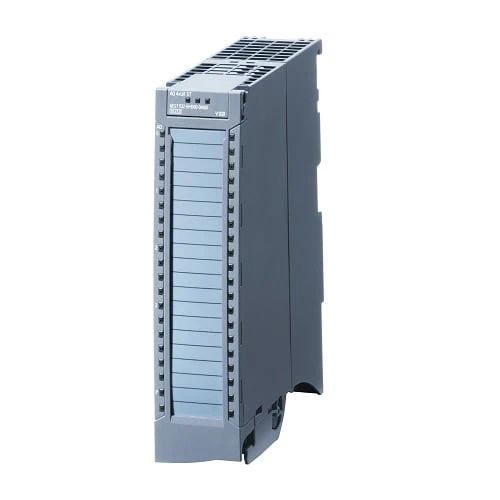
Analog output modules convert a 16-bit digital value into a current or a voltage and output this to the process. They are suitable, for example, for controlling proportional valves or small servo drives.
The following analog output modules are available:
| Article number | 6ES7532-5HD00-0AB0 | 6ES7532-5HF00-0AB0 | 6ES7532-5ND00-0AB0 | |
| S7-1500, AQ 4xU/I ST | S7-1500, AQ 8xU/I HS | S7-1500, AQ 4xU/I HF | ||
| General information | ||||
| Product type designation | AQ 4xU/I ST | AQ 8xU/I HS | AQ 4xU/I HF | |
| HW functional status | from FS04 | From FS01 | From FS01 | |
| Firmware version | V2.2.0 | V2.1.0 | V1.1.0 | |
| ● FW update possible | Yes | Yes | Yes | |
| Product function | ||||
| ● I&M data | Yes; I&M0 to I&M3 | Yes; I&M0 to I&M3 | Yes; I&M0 to I&M3 | |
| ● Isochronous mode | No | Yes | Yes | |
| ● Prioritized startup | No | No | Yes | |
| ● Output range scalable | No | No | ||
| Engineering with | ||||
| ● STEP 7 TIA Portal configurable/integrated from version | V12 / V12 | V14 / – | V14 / – | |
| ● STEP 7 configurable/integrated from version | V5.5 SP3 / – | V5.5 SP3 / – | V5.5 SP3 / – | |
| ● PROFIBUS from GSD version/GSD revision | V1.0 / V5.1 | V1.0 / V5.1 | V1.0 / V5.1 | |
| ● PROFINET from GSD version/GSD revision | V2.3 / – | V2.3 / – | V2.3 / – | |
| Operating mode | ||||
| ● Oversampling | No | Yes | No | |
| ● MSO | Yes | Yes | Yes | |
| CiR – Configuration in RUN | ||||
| Reparameterization possible in RUN | Yes | Yes | Yes | |
| Calibration possible in RUN | Yes | Yes | Yes | |
| Supply voltage | ||||
| Rated value (DC) | 24 V | 24 V | 24 V | |
| permissible range, lower limit (DC) | 19.2 V | 19.2 V | 19.2 V | |
| permissible range, upper limit (DC) | 28.8 V | 28.8 V | 28.8 V | |
| Reverse polarity protection | Yes | Yes | Yes | |
| Input current | ||||
| Current consumption, max. | 190 mA; with 24 V DC supply | 320 mA; with 19.2 V supply | 160 mA | |
| Power | ||||
| Power available from the backplane bus | 0.6 W | 1.15 W | 0.95 W | |
| Power loss | ||||
| Power loss, typ. | 4 W | 7 W | 5 W | |
| Analog outputs | ||||
| Number of analog outputs | 4 | 8 | 4 | |
| Voltage output, short-circuit protection | Yes | Yes | Yes | |
| Voltage output, short-circuit current, max. | 24 mA | 45 mA | 24 mA | |
| Current output, no-load voltage, max. | 22 V | 20 V | 22 V | |
| Cycle time (all channels), min. | 3.2 ms; independent of number of activated channels | 125 µs; independent of number of activated channels | 125 µs; independent of number of activated channels | |
| Output ranges, voltage | ||||
| ● 0 to 10 V | Yes | Yes | Yes | |
| ● 1 V to 5 V | Yes | Yes | Yes | |
| ● -5 V to +5 V | No | No | No | |
| ● -10 V to +10 V | Yes | Yes | Yes | |
| Output ranges, current | ||||
| ● 0 to 20 mA | Yes | Yes | Yes | |
| ● -20 mA to +20 mA | Yes | Yes | Yes | |
| ● 4 mA to 20 mA | Yes | Yes | Yes | |
| Connection of actuators | ||||
| ● for voltage output two-wire connection | Yes | Yes | Yes | |
| ● for voltage output four-wire connection | Yes | Yes | Yes | |
| ● for current output two-wire connection | Yes | Yes | Yes | |
| Load impedance (in rated range of output) | ||||
| ● with voltage outputs, min. | 1 kΩ; 0.5 kOhm at 1 to 5 V | 1 kΩ | 1 kΩ; 0.5 kOhm at 1 to 5 V | |
| ● with voltage outputs, capacitive load, max. | 1 µF | 100 nF | 1 µF | |
| ● with current outputs, max. | 750 Ω | 500 Ω | 750 Ω | |
| ● with current outputs, inductive load, max. | 10 mH | 1 mH | 10 mH | |
| Cable length | ||||
| ● shielded, max. | 800 m; for current, 200 m for voltage | 200 m | 800 m; for current, 200 m for voltage | |
| Analog value generation for the outputs | ||||
| Integration and conversion time/resolution per channel | ||||
| ● Resolution with overrange (bit including sign), max. | 16 bit | 16 bit | 16 bit | |
| ● Conversion time (per channel) | 0.5 ms | 50 µs; independent of number of activated channels | 125 µs; independent of number of activated channels | |
| Settling time | ||||
| ● for resistive load | 1.5 ms | 30 µs; see additional description in the manual | 0.2 ms; see additional description in the manual | |
| ● for capacitive load | 2.5 ms | 100 µs; see additional description in the manual | 1.8 ms; see additional description in the manual | |
| ● for inductive load | 2.5 ms | 100 µs; see additional description in the manual | 2 ms; see additional description in the manual | |
| Errors/accuracies | ||||
| Output ripple (relative to output range, bandwidth 0 to 50 kHz), (+/-) | 0.02 % | 0.02 % | 0.02 % | |
| Linearity error (relative to output range), (+/-) | 0.15 % | 0.15 % | 0.015 % | |
| Temperature error (relative to output range), (+/-) | 0.002 %/K | 0.002 %/K | 0.002 %/K | |
| Crosstalk between the outputs, max. | -100 dB | -100 dB | -100 dB | |
| Repeat accuracy in steady state at 25 °C (relative to output range), (+/-) | 0.05 % | 0.05 % | 0.005 % | |
| note regarding accuracy | at temperatures below 0 °C, the figures for operating error and temperature error are doubled | at temperatures below 0 °C, the figures for operating error and temperature error are doubled | at temperatures below 0 °C, the figures for operating error and temperature error are doubled | |
| Operational error limit in overall temperature range | ||||
| ● Voltage, relative to output range, (+/-) | 0.3 % | 0.3 % | ±10 V; 0 V to 10 V: ±0.12%; 1 V to 5 V: ±0.1% | |
| ● Current, relative to output range, (+/-) | 0.3 % | 0.3 % | ±20 mA; 0 mA to 20 mA: ±0.2%; 4 mA to 20 mA: ±0.12% | |
| Basic error limit (operational limit at 25 °C) | ||||
| ● Voltage, relative to output range, (+/-) | 0.2 % | 0.2 % | 0.06 % | |
| ● Current, relative to output range, (+/-) | 0.2 % | 0.2 % | 0.1 % | |
| Isochronous mode | ||||
| Execution and activation time (TCO), min. | 100 µs | 100 µs | ||
| Bus cycle time (TDP), min. | 250 µs | 250 µs | ||
| Interrupts/diagnostics/status information | ||||
| Diagnostics function | Yes | Yes | Yes | |
| Substitute values connectable | Yes | Yes | Yes | |
| Alarms | ||||
| ● Diagnostic alarm | Yes | Yes | Yes | |
| Diagnoses | ||||
| ● Monitoring the supply voltage | Yes | Yes | Yes | |
| ● Wire-break | Yes; Only for output type “current” | Yes; Only for output type “current” | Yes; Only for output type “current” | |
| ● Short-circuit | Yes; Only for output type “voltage” | Yes; Only for output type “voltage” | Yes; Only for output type “voltage” | |
| ● Overflow/underflow | Yes | Yes | Yes | |
| Diagnostics indication LED | ||||
| ● RUN LED | Yes; green LED | Yes; green LED | Yes; green LED | |
| ● ERROR LED | Yes; red LED | Yes; red LED | Yes; red LED | |
| ● Monitoring of the supply voltage (PWR-LED) | Yes; green LED | Yes; green LED | Yes; green LED | |
| ● Channel status display | Yes; green LED | Yes; green LED | Yes; green LED | |
| ● for channel diagnostics | Yes; red LED | Yes; red LED | Yes; red LED | |
| ● for module diagnostics | Yes; red LED | Yes; red LED | Yes; red LED | |
| Potential separation | ||||
| Potential separation channels | ||||
| ● between the channels | No | No | Yes | |
| ● between the channels, in groups of | 4 | 8 | 1 | |
| ● between the channels and backplane bus | Yes | Yes | Yes | |
| ● Between the channels and load voltage L+ | Yes | Yes | Yes | |
| Permissible potential difference | ||||
| between different circuits | 60 V DC/30 V AC; insulation rated for 120 V AC basic insulation: between the channels and the supply voltage L+; between the channels and the backplane bus; between the channels | |||
| between S- and MANA (UCM) | 8 V DC | 8 V DC | ||
| Isolation | ||||
| Isolation tested with | 707 V DC (type test) | 707 V DC (type test) | 2 000 V DC between the channels and the supply voltage L+; 2 000 V DC between the channels and the backplane bus; 2 000 V DC between the channels; 707 V DC (type test) between the supply voltage L+ and the backplane bus | |
| Standards, approvals, certificates | ||||
| Suitable for safety-related tripping of standard modules | Yes; From FS05 | Yes; from FS04 | Yes; From FS03 | |
| Highest safety class achievable for safety-related tripping of standard modules | ||||
| ● Performance level according to ISO 13849-1 | PL d | PL d | PL d | |
| ● Category according to ISO 13849-1 | Cat. 3 | Cat. 3 | Cat. 3 | |
| ● SIL acc. to IEC 62061 | SIL 2 | SIL 2 | SIL 2 | |
| ● SILCL according to IEC 62061 | ||||
| ● remark on safety-oriented shutdown | https://support.industry.siemens.com/cs/de/de/view/39198632 | |||
| Ambient conditions | ||||
| Ambient temperature during operation | ||||
| ● horizontal installation, min. | -30 °C; From FS06 | -30 °C; From FS03 | -25 °C; From FS02 | |
| ● horizontal installation, max. | 60 °C | 60 °C | 60 °C | |
| ● vertical installation, min. | -30 °C; From FS06 | -30 °C; From FS03 | -25 °C; From FS02 | |
| ● vertical installation, max. | 40 °C | 40 °C | 40 °C | |
| Altitude during operation relating to sea level | ||||
| ● Installation altitude above sea level, max. | 5 000 m; Restrictions for installation altitudes > 2 000 m, see manual | 5 000 m; Restrictions for installation altitudes > 2 000 m, see manual | ||
| Dimensions | ||||
| Width | 35 mm | 35 mm | 35 mm | |
| Height | 147 mm | 147 mm | 147 mm | |
| Depth | 129 mm | 129 mm | 129 mm | |
| Weights | ||||
| Weight, approx. | 310 g | 325 g | 300 g | |
| Other | ||||
| Note: | ||||