$ 476.66
The fail-safe ET 200SP modules can be used to implement the safety-related application requirements as an integrated part of the overall automation. The safety functions required for fail-safe operation are integrated in the modules. Communication with the fail-safe SIMATIC S7 CPUs is performed by means of PROFIsafe. The modules can be operated both in centralized and distributed configurations.
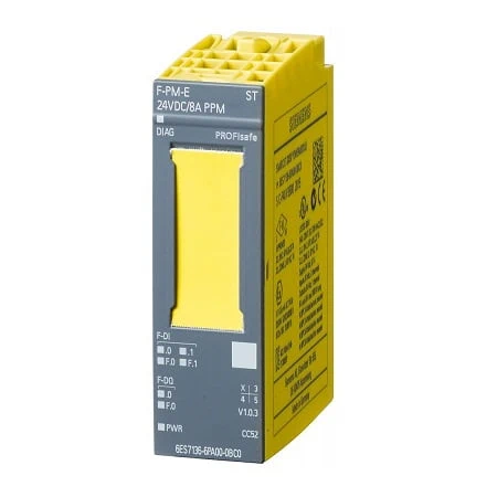
| Article number | 6ES7136-6PA00-0BC0 |
| ET 200SP, Powermod. F-PM-E PPM, 24V DC | |
| General information | |
| Product type designation | F-PM-E 24 V DC/8 A PPM ST |
| usable BaseUnits | BU type C0 |
| Color code for module-specific color identification plate | CC52 |
| Product function | |
| ● I&M data | Yes; I&M0 to I&M3 |
| Engineering with | |
| ● STEP 7 TIA Portal configurable/integrated from version | V12 |
| ● STEP 7 configurable/integrated from version | V5.5 SP3 / – |
| ● PROFINET from GSD version/GSD revision | V2.31 |
| Supply voltage | |
| Rated value (DC) | 24 V |
| permissible range, lower limit (DC) | 20.4 V |
| permissible range, upper limit (DC) | 28.8 V |
| Reverse polarity protection | Yes |
| Input current | |
| Current consumption (rated value) | 75 mA; without load |
| Current consumption, max. | 21 mA; From the backplane bus |
| output voltage / header | |
| Rated value (DC) | 24 V |
| Encoder supply | |
| Number of outputs | 2 |
| Short-circuit protection | Yes; Electronic (response threshold 0.7 A to 2.1 A) |
| Output current | |
| ● up to 60 °C, max. | 0.3 A |
| 24 V encoder supply | |
| ● 24 V | Yes; min. L+ (-1.5 V) |
| ● Short-circuit protection | Yes |
| ● Output current, max. | 600 mA; Total current of all encoders |
| Power | |
| Power available from the backplane bus | 70 mW |
| Power loss | |
| Power loss, typ. | 5 W |
| Address area | |
| Address space per module | |
| ● Inputs | 7 byte |
| ● Outputs | 5 byte |
| Hardware configuration | |
| Automatic encoding | Yes |
| ● Electronic coding element type F | Yes |
| Digital inputs | |
| Number of digital inputs | 2 |
| Source/sink input | Yes; P-reading |
| Input characteristic curve in accordance with IEC 61131, type 1 | Yes |
| Input voltage | |
| ● Type of input voltage | DC |
| ● Rated value (DC) | 24 V |
| ● for signal “0” | -30 to +5 V |
| ● for signal “1” | +15 to +30 V |
| Input current | |
| ● for signal “1”, typ. | 3.7 mA |
| Input delay (for rated value of input voltage) | |
| for standard inputs | |
| — parameterizable | Yes |
| — at “0” to “1”, min. | 0.4 ms |
| — at “0” to “1”, max. | 20 ms |
| — at “1” to “0”, min. | 0.4 ms |
| — at “1” to “0”, max. | 20 ms |
| for technological functions | |
| — parameterizable | No |
| Cable length | |
| ● shielded, max. | 1 000 m |
| ● unshielded, max. | 500 m |
| Digital outputs | |
| Number of digital outputs | 1 |
| Short-circuit protection | Yes |
| ● Response threshold, typ. | > 14.8 A |
| Open-circuit detection | Yes |
| ● Response threshold, typ. | 8 mA |
| Overload protection | Yes |
| ● Response threshold, typ. | 8.8 A |
| Limitation of inductive shutdown voltage to | Max. -1.5 V |
| Switching capacity of the outputs | |
| ● with resistive load, max. | 8 A |
| ● on lamp load, max. | 100 W |
| Load resistance range | |
| ● lower limit | 3 Ω |
| ● upper limit | 2 000 Ω |
| Output voltage | |
| ● for signal “1”, min. | 24 V; L+ (-0.5 V) |
| Output current | |
| ● for signal “1” rated value | 8 A |
| ● for signal “0” residual current, max. | 1.5 mA; PP-switching: max. 1.5 mA; PM-switching: max. 1 mA |
| Switching frequency | |
| ● with resistive load, max. | 10 Hz; Symmetrical |
| ● with inductive load, max. | 0.1 Hz; according to IEC 60947-5-1, DC-13, symmetrical |
| ● on lamp load, max. | 4 Hz; Symmetrical |
| Total current of the outputs | |
| ● Current per channel, max. | 8 A; note derating data in the manual |
| ● Current per module, max. | 8 A; note derating data in the manual |
| Cable length | |
| ● shielded, max. | 1 000 m |
| ● unshielded, max. | 500 m |
| Interrupts/diagnostics/status information | |
| Diagnostics function | Yes; See Chapter “Alarms/diagnostic messages” in the manual |
| Substitute values connectable | No |
| Alarms | |
| ● Diagnostic alarm | Yes |
| ● Hardware interrupt | No |
| Diagnostics indication LED | |
| ● RUN LED | Yes; green LED |
| ● ERROR LED | Yes; red LED |
| ● Monitoring of the supply voltage (PWR-LED) | Yes; green PWR LED |
| ● Channel status display | Yes; green LED |
| ● for channel diagnostics | Yes; red LED |
| ● for module diagnostics | Yes; green/red DIAG LED |
| Potential separation | |
| Potential separation channels | |
| ● between the channels | No |
| ● between the channels and backplane bus | Yes |
| ● between the channels and the power supply of the electronics | No |
| Isolation | |
| Isolation tested with | 707 V DC (type test) |
| Standards, approvals, certificates | |
| Suitable for safety functions | Yes |
| Highest safety class achievable in safety mode | |
| ● Performance level according to ISO 13849-1 | PLe |
| ● SIL acc. to IEC 61508 | SIL 3 |
| Ambient conditions | |
| Ambient temperature during operation | |
| ● horizontal installation, min. | 0 °C |
| ● horizontal installation, max. | 60 °C |
| ● vertical installation, min. | 0 °C |
| ● vertical installation, max. | 50 °C |
| Dimensions | |
| Width | 20 mm |
| Height | 73 mm |
| Depth | 55 mm |
| Weights | |
| Weight, approx. | 70 g |