USD 80.60 – USD 379.60Price range: USD 80.60 through USD 379.60
Scalable and cost-optimized configuration of a ET 200SP station is achieved by a comprehensive portfolio of digital and analog IO modules.
SIMATIC ET 200SP is about 50% narrower than other distributed peripheries. With its height of 115 millimeters, the system can accommodate 16 channels with single-wire connection (without AUX-plugs). For a 3-wire connection with AUX-plugs the height for 8 channels is 140 millimeters. The depth is 75 millimeters. In order to keep its small size, the power module for load group formation is integrated into the system of SIMATIC ET 200SP.
The peripheral modules are labelled with different colored squares to identify easily the type of module.
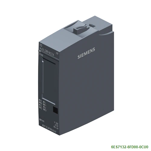
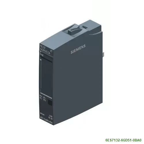
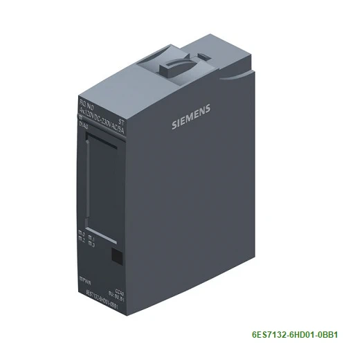
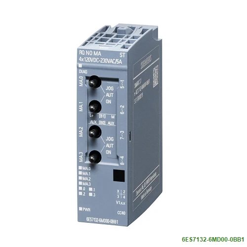
| Article number | 6ES7132-6FD00-0CU0 | 6ES7132-6GD51-0BA0 | 6ES7132-6HD01-0BB1 | 6ES7132-6MD00-0BB1 |
| ET 200SP, DQ 4×24..230VAC/2A HF, PU 1 | ET 200SP, RQ CO 4x 24V DC/2A ST, VPE 1 | ET 200SP, RQ NO 4x 120VDC..230VAC/5A,PU1 | ET 200SP,RQ NO-mA 4x120VDC..230VAC/5A ST | |
| General information | ||||
| Product type designation | DQ 4×24 … 230 V AC/2 A HF | RQ CO 4x24VDC/2A ST | RQ 4×120 VDC … 230 VAC/5 A NO ST | RQ 4×120 V DC … 230 V AC/5 A NO MA ST |
| HW functional status | From FS03 | From FS02 | From FS02 | From FS03 |
| Firmware version | V0.0 | V0.0 | ||
| ● FW update possible | Yes | No | No | Yes |
| usable BaseUnits | BU type U0 | BU type A0 | BU type B0, B1 | BU type B0, B1 |
| Color code for module-specific color identification plate | CC20 | CC00 | CC40 | CC40 |
| Product function | ||||
| ● I&M data | Yes; I&M0 to I&M3 | Yes; I&M0 to I&M3 | Yes; I&M0 to I&M3 | Yes; I&M0 to I&M3 |
| ● Isochronous mode | No | No | No | |
| Engineering with | ||||
| ● STEP 7 TIA Portal configurable/integrated from version | V14 | V14 | V14 | V13 SP1 |
| ● STEP 7 configurable/integrated from version | STEP 7 V5.5 or higher | V5.5 SP3 | V5.5 SP3 | V5.5 SP3 / – |
| ● PCS 7 configurable/integrated from version | V8.1 SP1 | |||
| ● PROFIBUS from GSD version/GSD revision | GSD as of Revision 5 | One GSD file each, Revision 3 and 5 and higher | One GSD file each, Revision 3 and 5 and higher | One GSD file each, Revision 3 and 5 and higher |
| ● PROFINET from GSD version/GSD revision | GSDML V2.3 | GSDML V2.3 | GSDML V2.3 | GSDML V2.3 |
| Operating mode | ||||
| ● DQ | Yes | Yes | Yes | Yes |
| ● DQ with energy-saving function | Yes | No | No | No |
| ● PWM | No | No | No | No |
| ● Oversampling | No | No | No | No |
| ● MSO | No | No | No | No |
| ● Phase control | Yes; Control area: 8.5 … 100% of the phase angle | |||
| ● Trailing-edge phase | No | |||
| ● Half-wave | Yes | |||
| ● Full-wave | Yes | |||
| Redundancy | ||||
| ● Redundancy capability | Yes | Yes | ||
| Supply voltage | ||||
| Rated value (DC) | 24 V | 24 V | 24 V | |
| permissible range, lower limit (DC) | 19.2 V | 19.2 V | 19.2 V | |
| permissible range, upper limit (DC) | 28.8 V | 28.8 V | 28.8 V | |
| Rated value (AC) | 230 V; 47 … 63 Hz, max. rate of change of frequency 1 mHz/s | |||
| permissible range, lower limit (AC) | 20.4 V | |||
| permissible range, upper limit (AC) | 264 V | |||
| Reverse polarity protection | Yes | Yes | Yes | |
| Input current | ||||
| Current consumption (rated value) | 8 mA; without load | 50 mA | 55 mA; without load | |
| Current consumption, max. | 100 mA; without load | |||
| output voltage / header | ||||
| Rated value (AC) | 230 V; 24V AC to 230V AC | 230 V | ||
| Power loss | ||||
| Power loss, typ. | 9 W; Active power, load voltage 230 V, all outputs loaded with 2 A, 50 Hz | 1.2 W | 1.5 W | 1.5 W |
| Address area | ||||
| Address space per module | ||||
| ● Inputs | + 1 byte for QI information | + 1 byte for QI information | + 1 byte for QI information | 1 byte; + 1 byte for QI information |
| ● Outputs | 8 byte | 1 byte | 1 byte | 1 byte |
| Hardware configuration | ||||
| Automatic encoding | Yes | Yes | Yes | Yes |
| ● Mechanical coding element | Yes | Yes | Yes | Yes |
| ● Type of mechanical coding element | type C | type C | type C | type C |
| Selection of BaseUnit for connection variants | ||||
| ● 1-wire connection | BU type U0 | |||
| ● 2-wire connection | BU type U0 | BU type B1 | BU type B1 | |
| ● 3-wire connection | BU type U0 + Potential distributor module | BU type B0 | BU type B0 | |
| Digital outputs | ||||
| Type of digital output | Triac | Relays | Relays | Relays |
| Number of digital outputs | 4 | 4 | 4 | 4 |
| Current-sinking | No | Yes | Yes | |
| Current-sourcing | Yes | Yes | Yes | |
| Digital outputs, parameterizable | Yes | Yes | Yes | |
| Short-circuit protection | No; external fusing necessary | No | No | No |
| Open-circuit detection | Yes; channel by channel | |||
| ● Response threshold, typ. | 1 mA; 40 V AC or more | |||
| Overload protection | No; A miniature fuse with 10 tripping current and tripping characteristic “quick response” must be provided in the module supply | |||
| Controlling a digital input | Yes | |||
| Switching capacity of the outputs | ||||
| ● with resistive load, max. | 2 A; Max. 4 A, see additional description in manual | |||
| ● with inductive load, max. | 2 A | |||
| ● on lamp load, max. | 100 W; Tungsten rating in accordance with UL; for thermistors with higher power ratings, see the notes in the manual | |||
| Output voltage | ||||
| ● for signal “1”, min. | 20.4 V | |||
| Output current | ||||
| ● for signal “1” rated value | 2 A | |||
| ● for signal “1” permissible range, min. | 10 mA | |||
| ● for signal “1” permissible range, max. | 4 A; note derating data in the manual | |||
| ● for signal “0” residual current, max. | 3 mA | |||
| Output delay with resistive load | ||||
| ● “0” to “1”, max. | 40 ms; 2 AC cycles | |||
| ● “1” to “0”, max. | 20 ms; 1 AC cycle | |||
| Parallel switching of two outputs | ||||
| ● for logic links | No | Yes | Yes | |
| ● for uprating | No | No | No | |
| ● for redundant control of a load | Yes | Yes | Yes | |
| Switching frequency | ||||
| ● with resistive load, max. | 10 Hz; Applies to DQ mode; limited by line frequency in PC mode | 2 Hz | 2 Hz | 2 Hz |
| ● with inductive load, max. | 0.5 Hz | 0.5 Hz | ||
| ● with inductive load (acc. to IEC 60947-5-1, AC15), max. | 10 Hz; Applies to DQ mode; limited by line frequency in PC mode | |||
| ● on lamp load, max. | 1 Hz; Applies to DQ mode; limited by line frequency in PC mode | 2 Hz | 2 Hz | |
| Total current of the outputs | ||||
| ● Current per channel, max. | 2 A; Max. 4 A, see additional description in manual | 2 A | 5 A | 5 A |
| ● Current per module, max. | 8 A | 8 A | 20 A | 20 A |
| Total current of the outputs (per module) | ||||
| horizontal installation | ||||
| — up to 40 °C, max. | 8 A | 8 A | ||
| — up to 50 °C, max. | 6 A | 6 A | 20 A | 20 A |
| — up to 60 °C, max. | 4 A | 4 A | 16 A | 16 A |
| vertical installation | ||||
| — up to 30 °C, max. | 8 A | 8 A | ||
| — up to 40 °C, max. | 6 A | 6 A | 20 A | 20 A |
| — up to 50 °C, max. | 4 A | 4 A | 16 A | 16 A |
| Relay outputs | ||||
| ● Number of relay outputs | 4 | 4 | 4 | |
| ● Rated supply voltage of relay coil L+ (DC) | 24 V | 24 V | 24 V | |
| ● Current consumption of relays (coil current of all relays), max. | 40 mA | 40 mA | 40 mA | |
| ● external protection for relay outputs | Yes, with miniature fuse max. 6 A tripping current and quick-response tripping characteristic | Yes, with miniature fuse max. 6 A tripping current and quick-response tripping characteristic | ||
| ● Number of operating cycles, max. | 500 000 | 7 000 000; see additional description in the manual | 7 000 000; see additional description in the manual | |
| Switching capacity of contacts | ||||
| — with inductive load, max. | 2 A; see additional description in the manual | 2 A; see additional description in the manual | ||
| — with resistive load, max. | 2 A | 5 A; see additional description in the manual | 5 A; see additional description in the manual | |
| — Thermal continuous current, max. | 2 A | 5 A; Max. 1 385 VA, 150 W | 5 A | |
| — Switching current, min. | 1 mA; 5 V DC | 100 mA; 5 V DC | 100 mA; 5 V DC | |
| — Rated switching voltage (DC) | 24 V | 24 V DC to 120 V DC | 24 V DC to 120 V DC | |
| — Rated switching voltage (AC) | 24 V | 24V AC to 230V AC | 24V AC to 230V AC | |
| Cable length | ||||
| ● shielded, max. | 1 000 m | 1 000 m | 1 000 m | 1 000 m |
| ● unshielded, max. | 600 m | 200 m | 200 m | 200 m |
| Interrupts/diagnostics/status information | ||||
| Diagnostics function | Yes | Yes | Yes | Yes |
| Substitute values connectable | Yes | Yes | Yes | Yes |
| Alarms | ||||
| ● Diagnostic alarm | Yes | Yes | Yes | Yes |
| Diagnoses | ||||
| ● Diagnostic information readable | Yes | |||
| ● Monitoring the supply voltage | Yes | Yes | Yes | Yes |
| ● Wire-break | Yes; channel by channel | No | No | No |
| ● Short-circuit | No | No | No | No |
| ● Group error | Yes | Yes | ||
| Diagnostics indication LED | ||||
| ● Monitoring of the supply voltage (PWR-LED) | Yes; green PWR LED | Yes; green PWR LED | Yes; green PWR LED | Yes; green PWR LED |
| ● Channel status display | Yes; green LED | Yes; green LED | Yes; green LED | Yes; green LED |
| ● for channel diagnostics | Yes; red Fn LED | No | No | No |
| ● for module diagnostics | Yes; green/red DIAG LED | Yes; green/red DIAG LED | Yes; green/red DIAG LED | Yes; green/red DIAG LED |
| Potential separation | ||||
| Potential separation channels | ||||
| ● between the channels | No | Yes | Yes | Yes |
| ● between the channels and backplane bus | Yes | Yes | Yes | Yes |
| ● between the channels and the power supply of the electronics | No | Yes | Yes | Yes |
| Permissible potential difference | ||||
| between channels and backplane bus/supply voltage | 240 V AC | 240 V AC | ||
| Isolation | ||||
| Isolation tested with | 2 545 V DC/2 s (routine test) | 707 V DC (type test) | 2 500 V DC (type test) | 2 500 V DC (type test) |
| tested with | ||||
| ● between channels and backplane bus/supply voltage | 2 500 V DC | 2 500 V DC | ||
| ● between backplane bus and supply voltage | 707 V DC (type test) | 707 V DC (type test) | ||
| Standards, approvals, certificates | ||||
| Suitable for safety functions | No | No | No | No |
| Ambient conditions | ||||
| Ambient temperature during operation | ||||
| ● horizontal installation, min. | -30 °C | -30 °C | -30 °C | -30 °C |
| ● horizontal installation, max. | 60 °C | 60 °C | 60 °C | 60 °C |
| ● vertical installation, min. | -30 °C | -30 °C | -30 °C | -30 °C |
| ● vertical installation, max. | 50 °C | 50 °C | 50 °C | 50 °C |
| Altitude during operation relating to sea level | ||||
| ● Installation altitude above sea level, max. | 2 000 m; On request: Installation altitudes greater than 2 000 m | 2 000 m; On request: Installation altitudes greater than 2 000 m | 2 000 m; On request: Installation altitudes greater than 2 000 m | 2 000 m; On request: Installation altitudes greater than 2 000 m |
| Dimensions | ||||
| Width | 20 mm | 15 mm | 20 mm | 20 mm |
| Height | 73 mm | 73 mm | 73 mm | 73 mm |
| Depth | 58 mm | 58 mm | 58 mm | 58 mm |
| Weights | ||||
| Weight, approx. | 50 g | 30 g | 40 g | 45 g |