USD 124.28 – USD 213.72Price range: USD 124.28 through USD 213.72
The signals from digital sensors (switches, inductive and optical sensors etc.) can be recorded and transferred to the higher-level controller via the digital input modules.
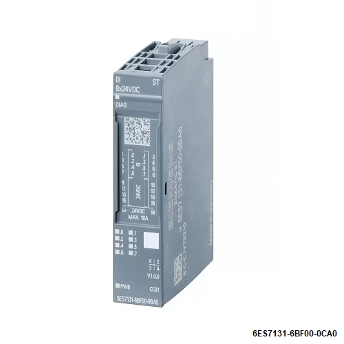
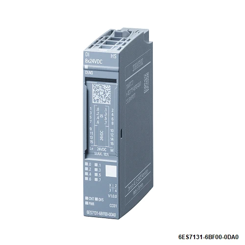
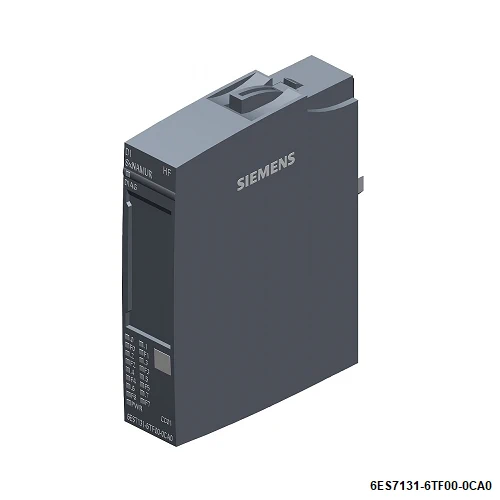
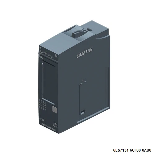
| Article number | 6ES7131-6BF00-0CA0 | 6ES7131-6BF00-0DA0 | 6ES7131-6TF00-0CA0 | 6ES7131-6FD01-0BB1 | 6ES7131-6CF00-0AU0 |
| ET 200SP, DI 8x24VDC HF, PU 1 | ET 200SP, DI 8x24VDC High Speed | ET 200SP, DI 8xNAMUR HF | ET 200SP, DI 4x 120..230VvAC ST | ET 200SP, DI 8x 24VAC..48VUC BA, PU 1 | |
| General information | |||||
| Product type designation | DI 8×24 V DC HF | DI 8×24 V DC HS | DI 8xNAMUR HF | DI 4×120 … 230 V AC ST | DI 8x24VAC/48VUC BA |
| HW functional status | From FS07 | from FS04 | from FS04 | From FS02 | From FS02 |
| Firmware version | V1.0.2 | V0.0 | V0.0 | ||
| ● FW update possible | Yes | Yes | Yes | No | No |
| usable BaseUnits | BU type A0 | BU type A0 | BU type A0 | BU type B1 | BU type U0 |
| Color code for module-specific color identification plate | CC01 | CC01 | CC01 | CC41 | |
| Product function | |||||
| ● I&M data | Yes; I&M0 to I&M3 | Yes; I&M0 to I&M3 | Yes; I&M0 to I&M3 | Yes; I&M0 to I&M3 | |
| ● Isochronous mode | Yes | Yes | No | No | No |
| Engineering with | |||||
| ● STEP 7 TIA Portal configurable/integrated from version | V13 SP1 / – | V13 SP1 | V13 / V13 | V14 | V15 |
| ● STEP 7 configurable/integrated from version | V5.5 / – | V5.5 SP3 / – | V5.5 SP3 / – | V5.5 SP3 | V5.6 |
| ● PCS 7 configurable/integrated from version | V8.1 SP1 | ||||
| ● PROFIBUS from GSD version/GSD revision | One GSD file each, Revision 3 and 5 and higher | One GSD file each, Revision 3 and 5 and higher | GSD Revision 5 | One GSD file each, Revision 3 and 5 and higher | One GSD file each, Revision 3 and 5 and higher |
| ● PROFINET from GSD version/GSD revision | GSDML V2.3 | GSDML V2.3 | GSDML V2.3 | GSDML V2.3 | GSDML V2.3 |
| Operating mode | |||||
| ● DI | Yes | Yes | Yes | Yes | Yes |
| ● Counter | No | Yes | No | No | No |
| ● Oversampling | No | Yes | No | No | No |
| ● MSI | Yes | No | No | No | No |
| Supply voltage | |||||
| Rated value (DC) | 24 V | 24 V | 24 V | 48 V | |
| permissible range, lower limit (DC) | 19.2 V | 19.2 V | 19.2 V | 40.8 V | |
| permissible range, upper limit (DC) | 28.8 V | 28.8 V | 28.8 V | 57.6 V | |
| Rated value (AC) | 230 V | 48 V; 24 V/48 V; 50 Hz/60 Hz | |||
| permissible range, lower limit (AC) | 187 V | 40.8 V | |||
| permissible range, upper limit (AC) | 264 V | 52.8 V | |||
| Reverse polarity protection | Yes | Yes | Yes | No | Yes |
| Input current | |||||
| Current consumption (rated value) | 10 mA | ||||
| Current consumption, max. | 70 mA; without sensor supply | 70 mA; without sensor supply | |||
| Encoder supply | |||||
| Number of outputs | 8 | 8 | 4 | 8 | |
| Output voltage, min. | 19.2 V | ||||
| Short-circuit protection | Yes | Yes | No; when using BU type B1, a fuse with 10 A tripping current must be provided | Yes; Per module, 5x 20 mm fuse, 2 A/250 V, quick-response, replaceable | |
| Output current | |||||
| ● up to 60 °C, max. | 10 A | 1 A | |||
| 24 V encoder supply | |||||
| ● 24 V | Yes | Yes | No | No | |
| ● Short-circuit protection | Yes; per channel, electronic | Yes; per module, electronic | No | ||
| ● Output current, max. | 700 mA | ||||
| ● Output current per channel, max. | 700 mA | ||||
| ● Output current per module, max. | 700 mA | ||||
| Power loss | |||||
| Power loss, typ. | 1.5 W; 24 V, 8 inputs supplied via encoder supply | 1.5 W | 1.5 W | 1 W; Active power, load voltage 230 V, all inputs connected with 230 V, 50 Hz | 1.5 W |
| Address area | |||||
| Address space per module | |||||
| ● Address space per module, max. | 45 byte | 1 byte; + 1 byte for QI information | 1 byte | ||
| ● Inputs | 1 byte; + 1 byte for QI information | 32 byte; 1 byte + 1 byte for QI information in DI mode; 32 bytes in Oversampling mode; 25 bytes in Counter mode | 1 byte; + 1 byte for QI information | ||
| ● Outputs | 20 byte; In count mode | ||||
| Hardware configuration | |||||
| Automatic encoding | Yes | Yes | Yes | ||
| ● Mechanical coding element | Yes | Yes | Yes | Yes | |
| ● Type of mechanical coding element | Type A | Type A | Type A | type C | type C |
| Submodules | |||||
| ● Number of configurable submodules, max. | 4 | ||||
| Selection of BaseUnit for connection variants | |||||
| ● 1-wire connection | BU type A0 | BU type A0 | BU type A0 | BU type B1 | BU type U0 |
| ● 2-wire connection | BU type A0 | BU type A0 | BU type A0 | BU type B1 | BU type U0 |
| ● 3-wire connection | BU type A0 with AUX terminals or potential distributor module | BU type A0 with AUX terminals | BU type A0 + external terminals | BU type B1 | BU type U0 + Potential distributor module |
| ● 4-wire connection | BU type A0 + Potential distributor module | BU type A0 + external terminals | BU type A0 + external terminals | BU type B1 + potential distributor module | BU type U0 + Potential distributor module |
| Digital inputs | |||||
| Number of digital inputs | 8 | 8 | 8; NAMUR | 4 | 8 |
| Digital inputs, parameterizable | Yes | Yes | |||
| Source/sink input | P-reading | P-reading | P-reading | ||
| Input characteristic curve in accordance with IEC 61131, type 1 | Yes | ||||
| Input characteristic curve in accordance with IEC 61131, type 2 | No | ||||
| Input characteristic curve in accordance with IEC 61131, type 3 | Yes | Yes | No | ||
| Pulse extension | Yes; Pulse duration from 4 µs | Yes | Yes; 0.5 s, 1 s, 2 s | No | |
| ● Length | 2 s; 50 ms, 100 ms, 200 ms, 500 ms, 1 s, 2 s | 2 s; 50 ms, 100 ms, 200 ms, 500 ms, 1 s, 2 s | |||
| Edge evaluation | Yes; rising edge, falling edge, edge change | Yes; rising edge, falling edge, edge change | |||
| Signal change flutter | Yes; 2 to 32 signal changes | ||||
| Flutter observation window | Yes; 0.5 s, 1 s to 100 s in 1-s steps | ||||
| Digital input functions, parameterizable | |||||
| ● Gate start/stop | Yes | ||||
| ● Freely usable digital input | Yes | ||||
| ● Counter | Yes | ||||
| — Number, max. | 4 | ||||
| — Counting frequency, max. | 10 kHz | ||||
| — Counting width | 32 bit | ||||
| — Counting direction up/down | Yes | ||||
| ● Digital input with oversampling | Yes | ||||
| — Number, max. | 8 | ||||
| — Values per cycle, max. | 32 | ||||
| — Resolution, min. | 7.8125 µs | ||||
| Input voltage | |||||
| ● Rated value (DC) | 24 V | 24 V | 8.2 V | ||
| ● Rated value (AC) | 230 V | ||||
| ● for signal “0” | -30 to +5 V | -30 to +5 V | 0V AC to 40V AC | AC/DC < 10 V | |
| ● for signal “1” | +11 to +30V | +11 to +30V | 74 V AC to 264 V AC | AC > 14 V, DC > 34 V | |
| Input current | |||||
| ● for signal “1”, typ. | 2.5 mA | 6 mA | 10.8 mA | 3.5 mA | |
| for 10 k switched contact | |||||
| — for signal “0” | 0.35 to 1.2 mA | ||||
| — for signal “1” | 2.1 to 7 mA | ||||
| for unswitched contact | |||||
| — for signal “0”, max. (permissible quiescent current) | 0.5 mA | ||||
| — for signal “1” | typ. 8 mA | ||||
| for NAMUR encoders | |||||
| — for signal “0”, min. | 0.35 mA | ||||
| — for signal “0”, max. | 1.2 mA | ||||
| — for signal “1”, min. | 2.1 mA | ||||
| — for signal “1”, max. | 7 mA | ||||
| Input delay (for rated value of input voltage) | |||||
| ● tolerated changeover time for changeover contacts | 300 ms | ||||
| for standard inputs | |||||
| — parameterizable | Yes; 0.05 / 0.1 / 0.4 / 0.8 / 1.6 / 3.2 / 12.8 / 20 ms (in each case + delay of 30 to 500 µs, depending on line length) | Yes; none / 0.05 / 0.1 / 0.4 / 0.8 / 1.6 / 3.2 / 12.8 / 20 ms | No | No | No |
| — at “0” to “1”, min. | 0.05 ms | 1.5 ms | |||
| — at “0” to “1”, max. | 20 ms | 4 ms | 15 ms | ||
| — at “1” to “0”, min. | 0.05 ms | 10 ms | |||
| — at “1” to “0”, max. | 20 ms | 10 ms | 20 ms | ||
| for interrupt inputs | |||||
| — parameterizable | Yes | ||||
| for technological functions | |||||
| — parameterizable | Yes | ||||
| for NAMUR inputs | |||||
| — at “0” to “1”, max. | 12 ms | ||||
| — at “1” to “0”, max. | 12 ms | ||||
| Cable length | |||||
| ● shielded, max. | 1 000 m | 50 m | 200 m | 1 000 m | 1 000 m |
| ● unshielded, max. | 600 m | 50 m | 600 m | 600 m | |
| Encoder | |||||
| Connectable encoders | |||||
| ● NAMUR encoder/changeover contact according to EN 60947 | Yes | ||||
| ● Single contact / changeover contact unconnected | Yes | ||||
| ● Single contact / changeover contact connected with 10 kΩ | Yes | ||||
| ● 2-wire sensor | Yes | Yes | Yes | Yes | |
| — permissible quiescent current (2-wire sensor), max. | 1.5 mA | 1.5 mA | |||
| Isochronous mode | |||||
| Filtering and processing time (TCI), min. | 420 µs | ||||
| Bus cycle time (TDP), min. | 500 µs | 125 µs | |||
| Jitter, max. | 8 µs | 5 µs | |||
| Interrupts/diagnostics/status information | |||||
| Diagnostics function | Yes | Yes | Yes | Yes | |
| Alarms | |||||
| ● Diagnostic alarm | Yes; channel by channel | Yes | Yes; channel by channel | No | Yes |
| ● Hardware interrupt | Yes; Parameterizable, channels 0 to 7 | Yes | Yes; Parameterizable, channels 0 to 7 | No | |
| Diagnoses | |||||
| ● Diagnostic information readable | Yes | Yes | Yes | Yes | |
| ● Monitoring the supply voltage | Yes | Yes | Yes | No | Yes |
| — parameterizable | Yes | Yes | Yes | ||
| ● Monitoring of encoder power supply | Yes; channel by channel | Yes; Module-wise | No | Yes | |
| ● Wire-break | Yes; Channel by channel, optional protective circuit for preventing wire-break diagnostics in the case of simple encoder contacts: 25 kOhm to 45 kOhm | No | Yes; channel by channel | No | |
| ● Short-circuit | Yes; channel by channel | Yes; Module-wise | Yes; channel by channel | No | |
| ● Group error | Yes | ||||
| Diagnostics indication LED | |||||
| ● Monitoring of the supply voltage (PWR-LED) | Yes; green PWR LED | Yes; green PWR LED | Yes; green PWR LED | Yes; green PWR LED | Yes; green PWR LED |
| ● Channel status display | Yes; green LED | Yes; green LED | Yes; green LED | Yes; green LED | Yes; green LED |
| ● for channel diagnostics | Yes; red LED | No | Yes; red LED | No | No |
| ● for module diagnostics | Yes; green/red DIAG LED | Yes; green/red DIAG LED | Yes; green/red DIAG LED | Yes; green/red DIAG LED | Yes; green/red DIAG LED |
| Potential separation | |||||
| Potential separation channels | |||||
| ● between the channels | No | No | No | No | No |
| ● between the channels and backplane bus | Yes | Yes | Yes | Yes | Yes |
| ● between the channels and the power supply of the electronics | No | No | Yes | No | No |
| Isolation | |||||
| Isolation tested with | 707 V DC (type test) | 707 V DC (type test) | 707 V DC (type test) | 2 545 V DC/2 s (routine test) | 1 200 V DC between supply voltage and backplane bus |
| Standards, approvals, certificates | |||||
| Suitable for safety functions | No | No | No | No | No |
| Ambient conditions | |||||
| Ambient temperature during operation | |||||
| ● horizontal installation, min. | -30 °C; < 0 °C as of FS07 | -30 °C; < 0 °C as of FS04 | -30 °C | -30 °C | -30 °C |
| ● horizontal installation, max. | 60 °C | 60 °C | 60 °C | 60 °C | 60 °C |
| ● vertical installation, min. | -30 °C; < 0 °C as of FS07 | -30 °C; < 0 °C as of FS04 | -30 °C | -30 °C | -30 °C |
| ● vertical installation, max. | 50 °C | 50 °C | 50 °C | 50 °C | 50 °C |
| Altitude during operation relating to sea level | |||||
| ● Installation altitude above sea level, max. | 5 000 m; Restrictions for installation altitudes > 2 000 m, see manual | 5 000 m; Restrictions for installation altitudes > 2 000 m, see manual | 5 000 m; Restrictions for installation altitudes > 2 000 m, see manual | 2 000 m; On request: Installation altitudes greater than 2 000 m | 2 000 m; On request: Installation altitudes greater than 2 000 m |
| Dimensions | |||||
| Width | 15 mm | 15 mm | 15 mm | 20 mm | 20 mm |
| Height | 73 mm | 73 mm | 73 mm | 73 mm | 73 mm |
| Depth | 58 mm | 58 mm | 58 mm | 58 mm | 58 mm |
| Weights | |||||
| Weight, approx. | 28 g | 28 g | 32 g | 36 g | 40 g |