$ 492.50
The fail-safe ET 200SP modules can be used to implement the safety-related application requirements as an integrated part of the overall automation. The safety functions required for fail-safe operation are integrated in the modules. Communication with the fail-safe SIMATIC S7 CPUs is performed by means of PROFIsafe.
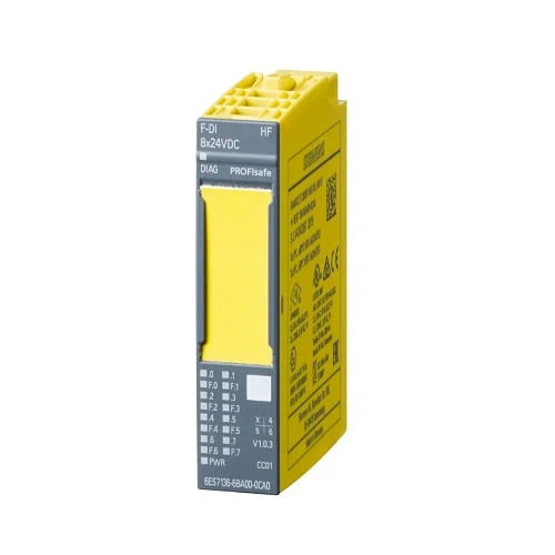
| Article number | 6ES7136-6BA00-0CA0 | |
| ET 200SP, El-Mod., F-DI 8x24VDC HF | ||
| General information | ||
| Product type designation | F-DI 8x24VDC HF | |
| Firmware version | ||
| ● FW update possible | ||
| usable BaseUnits | BU type A0 | |
| Color code for module-specific color identification plate | ||
| Product function | ||
| ● I&M data | Yes; I&M0 to I&M3 | |
| Engineering with | ||
| ● STEP 7 TIA Portal configurable/integrated from version | V12 | |
| ● STEP 7 configurable/integrated from version | V5.5 SP3 / – | |
| ● PROFINET from GSD version/GSD revision | V2.31 | |
| CiR – Configuration in RUN | ||
| Reparameterization possible in RUN | ||
| Supply voltage | ||
| Rated value (DC) | 24 V | |
| permissible range, lower limit (DC) | 20.4 V | |
| permissible range, upper limit (DC) | 28.8 V | |
| Reverse polarity protection | Yes | |
| power supply according to NEC Class 2 required | No | |
| Input current | ||
| Current consumption (rated value) | 75 mA; without load | |
| Current consumption, max. | 21 mA; From the backplane bus | |
| Encoder supply | ||
| Number of outputs | 8 | |
| Short-circuit protection | Yes; Electronic (response threshold 0.7 A to 1.8 A) | |
| Output current | ||
| ● up to 60 °C, max. | 0.3 A | |
| 24 V encoder supply | ||
| ● 24 V | Yes; min. L+ (-1.5 V) | |
| ● Short-circuit protection | Yes | |
| ● Output current, max. | 800 mA; Total current of all encoders | |
| ● Output current per channel, max. | ||
| ● Output current per module, max. | ||
| Power | ||
| Power available from the backplane bus | 70 mW | |
| Power loss | ||
| Power loss, typ. | 4 W | |
| Address area | ||
| Address space per module | ||
| ● Inputs | 6 byte | |
| ● Outputs | 4 byte | |
| Hardware configuration | ||
| Automatic encoding | Yes | |
| ● Electronic coding element type F | Yes | |
| Digital inputs | ||
| Number of digital inputs | 8 | |
| Source/sink input | Yes; P-reading | |
| Input characteristic curve in accordance with IEC 61131, type 1 | Yes | |
| Input voltage | ||
| ● Rated value (DC) | 24 V | |
| ● for signal “0” | -30 to +5 V | |
| ● for signal “1” | +15 to +30 V | |
| Input current | ||
| ● for signal “1”, typ. | 3.7 mA | |
| Input delay (for rated value of input voltage) | ||
| for standard inputs | ||
| — parameterizable | Yes | |
| — at “0” to “1”, min. | 0.4 ms | |
| — at “0” to “1”, max. | 20 ms | |
| — at “1” to “0”, min. | 0.4 ms | |
| — at “1” to “0”, max. | 20 ms | |
| for technological functions | ||
| — parameterizable | No | |
| Cable length | ||
| ● shielded, max. | 1 000 m | |
| ● unshielded, max. | 500 m | |
| Interrupts/diagnostics/status information | ||
| Diagnostics function | Yes | |
| Alarms | ||
| ● Diagnostic alarm | Yes | |
| ● Hardware interrupt | No | |
| Diagnostics indication LED | ||
| ● RUN LED | Yes; green LED | |
| ● ERROR LED | Yes; red LED | |
| ● Monitoring of the supply voltage (PWR-LED) | Yes; green PWR LED | |
| ● Channel status display | Yes; green LED | |
| ● for channel diagnostics | Yes; red LED | |
| ● for module diagnostics | Yes; green/red DIAG LED | |
| Potential separation | ||
| Potential separation channels | ||
| ● between the channels | No | |
| ● between the channels and backplane bus | Yes | |
| ● between the channels and the power supply of the electronics | No | |
| Isolation | ||
| Isolation tested with | 707 V DC (type test) | |
| Standards, approvals, certificates | ||
| Suitable for safety functions | Yes | |
| Highest safety class achievable in safety mode | ||
| ● Performance level according to ISO 13849-1 | PLe | |
| ● Category according to ISO 13849-1 | ||
| ● SIL acc. to IEC 61508 | SIL 3 | |
| Probability of failure (for service life of 20 years and repair time of 100 hours) | ||
| — Low demand mode: PFDavg in accordance with SIL3 | < 2.00E-05 | |
| — High demand/continuous mode: PFH in accordance with SIL3 | < 1.00E-09 1/h | |
| Ambient conditions | ||
| Ambient temperature during operation | ||
| ● horizontal installation, min. | 0 °C | |
| ● horizontal installation, max. | 60 °C | |
| ● vertical installation, min. | 0 °C | |
| ● vertical installation, max. | 50 °C | |
| Altitude during operation relating to sea level | ||
| ● Installation altitude above sea level, max. | 4 000 m; Restrictions for installation altitudes > 2 000 m, see manual | |
| Dimensions | ||
| Width | 15 mm | |
| Height | 73 mm | |
| Depth | 58 mm | |
| Weights | ||
| Weight, approx. | 49 g | |