USD 335.66
The CM 4x IO-Link communications module enables data exchange with up to 4 external IO-Link devices via one 3-wire cable each. Comprehensive parameterization options make it possible to adapt the controller flexibly to the communication partner. Thanks to the compatibility of IO-Link with standard sensors, commercially available sensors in accordance with IEC 61131 Type 1 can also be operated on the IO-Link master.
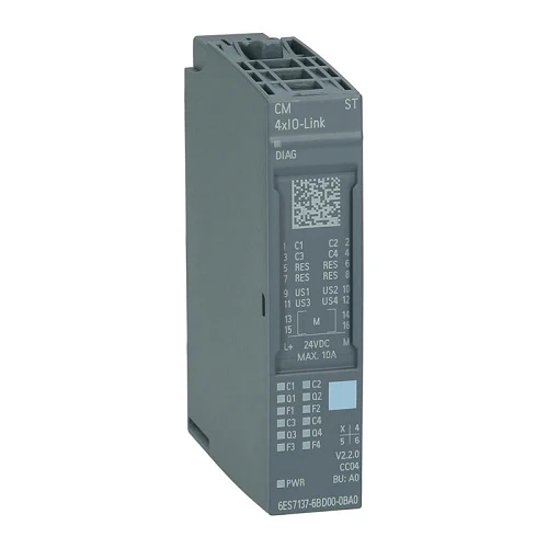
| Article number | 6ES7137-6BD00-0BA0 |
| ET 200SP, cm 4 X IO-Link ST | |
| General information | |
| Product type designation | CM 4 x IO-Link ST |
| HW functional status | FS20 |
| Firmware version | V2.2.2 |
| ● FW update possible | Yes |
| usable BaseUnits | BU type A0 |
| Color code for module-specific color identification plate | CC04 |
| Product function | |
| ● I&M data | Yes; I&M0 to I&M3 |
| ● Isochronous mode | No; Only for PROFINET and configuration as version with FW V2.0 or V2.1 |
| Engineering with | |
| ● STEP 7 TIA Portal configurable/integrated from version | STEP 7 V15 or higher |
| ● STEP 7 configurable/integrated from version | STEP 7 V5.5 or higher |
| ● PROFIBUS from GSD version/GSD revision | One GSD file each, Revision 3 and 5 and higher |
| ● PROFINET from GSD version/GSD revision | GSDML V2.3 |
| Supply voltage | |
| Rated value (DC) | 24 V |
| permissible range, lower limit (DC) | 19.2 V; 20.5 V if IO-Link is used, as the supply voltage for IO-Link devices has to be at least 20 V at the master. |
| permissible range, upper limit (DC) | 28.8 V |
| power supply according to NEC Class 2 required | No |
| Input current | |
| Current consumption, max. | 45 mA; without load |
| Encoder supply | |
| Number of outputs | 4 |
| Output current | |
| ● Rated value | 700 mA; Per channel |
| 24 V encoder supply | |
| ● Short-circuit protection | Yes |
| ● Output current, max. | 2.1 A |
| Power loss | |
| Power loss, typ. | 1 W |
| Hardware configuration | |
| Automatic encoding | Yes |
| ● Electronic coding element type H | Yes |
| Digital outputs | |
| Cable length | |
| ● unshielded, max. | 20 m; Also applies for shielded cables |
| IO-Link | |
| Number of ports | 4 |
| ● of which simultaneously controllable | 4 |
| IO-Link protocol 1.0 | Yes |
| IO-Link protocol 1.1 | Yes |
| Transmission rate | 4.8 kBaud (COM1); 38.4 kBaud (COM2), 230.4 kBaud (COM3) |
| Cycle time, min. | 2 ms; dynamic, depending on user data length |
| Size of process data, input per port | 32 byte; max. |
| Size of process data, input per module | 144 byte; max. |
| Size of process data, output per port | 32 byte; max. |
| Size of process data, output per module | 128 byte; max. |
| Memory size for device parameter | 2 kbyte; for each port |
| Master backup | Yes |
| Configuration without S7-PCT | Yes |
| Cable length unshielded, max. | 20 m |
| Operating modes | |
| ● IO-Link | Yes |
| ● DI | Yes |
| ● DQ | Yes; max. 100 mA per channel |
| Time Based IO | |
| — TIO IO-Link IN | No; Only for PROFINET and configuration as version with FW V2.0 or V2.1 |
| — TIO IO-Link OUT | No; Only for PROFINET and configuration as version with FW V2.0 or V2.1 |
| — TIO IO-Link IN/OUT | No; Only for PROFINET and configuration as version with FW V2.0 or V2.1 |
| Connection of IO-Link devices | |
| ● Port type A | Yes |
| ● Port type B | Yes; 24 V DC via external terminal |
| ● via three-wire connection | Yes |
| Interrupts/diagnostics/status information | |
| Alarms | |
| ● Diagnostic alarm | Yes; The port diagnosis is available in the IO-Link mode only. |
| Diagnoses | |
| ● Monitoring the supply voltage | Yes |
| ● Wire-break | Yes |
| ● Short-circuit | Yes |
| ● Group error | Yes |
| Diagnostics indication LED | |
| ● Monitoring of the supply voltage (PWR-LED) | Yes; green PWR LED |
| ● Channel status display | Yes; one green LED for channel status Qn (SIO mode) and port status Cn (IO-Link mode) per channel |
| ● for channel diagnostics | Yes; red Fn LED |
| ● for module diagnostics | Yes; green/red DIAG LED |
| Potential separation | |
| Potential separation channels | |
| ● between the channels | No |
| ● between the channels and backplane bus | Yes |
| ● between the channels and the power supply of the electronics | No |
| Isolation | |
| Isolation tested with | 707 V DC (type test) |
| Ambient conditions | |
| Ambient temperature during operation | |
| ● horizontal installation, min. | -30 °C |
| ● horizontal installation, max. | 60 °C |
| ● vertical installation, min. | -30 °C |
| ● vertical installation, max. | 50 °C |
| Altitude during operation relating to sea level | |
| ● Installation altitude above sea level, max. | 2 000 m; On request: Installation altitudes greater than 2 000 m |
| Dimensions | |
| Width | 13 mm |
| Height | 73 mm |
| Depth | 58 mm |
| Weights | |
| Weight, approx. | 30 g |