$ 38.00 – $ 58.00Price range: $ 38.00 through $ 58.00
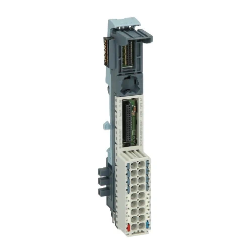
With the BaseUnits (BUs), the ET 200SP offers a rugged and service-friendly design with permanent wiring:
An ET 200SP station can be expanded via one ‘BU-Send’ BaseUnit with a “BA-Send” BusAdapter plugged onto it with up to 16 modules from the ET 200AL series of I/O devices with IP67 protection.
| Article number | 6ES7193-6BP40-0DA1 | 6ES7193-6BP00-0DA1 | 6ES7193-6BP40-0BA1 | 6ES7193-6BP00-0BA1 |
| BaseUnit Type A1, BU15-P16+A0+12D/T | BaseUnit Type A1, BU15-P16+A0+2D/T | BaseUnit Type A1, BU15-P16+A0+12B/T | BaseUnit Type A1, BU15-P16+A0+2B/T | |
| General information | ||||
| Product type designation | BU type A1 | BU type A1 | BU type A1 | BU type A1 |
| HW functional status | FS10 and higher | FS10 and higher | FS10 and higher | FS10 and higher |
| Supply voltage | ||||
| Rated value (DC) | 24 V | 24 V | 24 V | 24 V |
| external protection for power supply lines | Yes; 24 V DC/10 A miniature circuit breaker with type B or C tripping characteristic | Yes; 24 V DC/10 A miniature circuit breaker with type B or C tripping characteristic | Yes; 24 V DC/10 A miniature circuit breaker with type B or C tripping characteristic | Yes; 24 V DC/10 A miniature circuit breaker with type B or C tripping characteristic |
| Current carrying capacity | ||||
| For P1 and P2 bus, max. | 10 A | 10 A | 10 A | 10 A |
| For process terminals, max. | 2 A | 2 A | 2 A | 2 A |
| Hardware configuration | ||||
| Additional terminals | Yes | Yes | ||
| Temperature sensor | Yes | Yes | Yes | Yes |
| Formation of potential groups | ||||
| ● New potential group | Yes | Yes | No | No |
| ● Potential group continued from the left | No | No | Yes | Yes |
| Slots | ||||
| ● Number of slots | 1; Type A1 | 1; Type A1 | 1; Type A1 | 1; Type A1 |
| Potential separation | ||||
| between the potential groups | Yes | Yes | ||
| Isolation | ||||
| Isolation tested with | 707 V DC (type test) | 707 V DC (type test) | 707 V DC (type test) | 707 V DC (type test) |
| Ambient conditions | ||||
| Ambient temperature during operation | ||||
| ● horizontal installation, min. | -30 °C | -30 °C | -30 °C | -30 °C |
| ● horizontal installation, max. | 60 °C | 60 °C | 60 °C | 60 °C |
| ● vertical installation, min. | -30 °C | -30 °C | -30 °C | -30 °C |
| ● vertical installation, max. | 50 °C | 50 °C | 50 °C | 50 °C |
| Altitude during operation relating to sea level | ||||
| ● Installation altitude above sea level, max. | 5 000 m; Restrictions for installation altitudes > 2 000 m, see manual | 5 000 m; Restrictions for installation altitudes > 2 000 m, see manual | 5 000 m; Restrictions for installation altitudes > 2 000 m, see manual | 5 000 m; Restrictions for installation altitudes > 2 000 m, see manual |
| Accessories | ||||
| Color coding labels | ||||
| ● for process terminals | CC00 to CC09 | CC00 to CC09 | CC00 to CC09 | CC00 to CC09 |
| ● for AUX terminals | does not exist | does not exist | does not exist | does not exist |
| ● for add-on terminals | CC74 | does not exist | CC74 | does not exist |
| connection method / header | ||||
| Terminals | ||||
| ● Terminal type | Push-in terminal | Push-in terminal | Push-in terminal | Push-in terminal |
| ● Conductor cross-section, min. | 0.14 mm²; AWG 26 | 0.14 mm²; AWG 26 | 0.14 mm²; AWG 26 | 0.14 mm²; AWG 26 |
| ● Conductor cross-section, max. | 2.5 mm²; AWG 14 | 2.5 mm²; AWG 14 | 2.5 mm²; AWG 14 | 2.5 mm²; AWG 14 |
| ● Number of process terminals to I/O module | 16 | 16 | 16 | 16 |
| ● Number of terminals to AUX bus | 0 | 0 | 0 | 0 |
| ● Number of add-on terminals | 2×5 | 0 | 2×5 | 0 |
| ● Number of terminals with connection to P1 and P2 bus | 2 | 2 | 2 | 2 |
| Dimensions | ||||
| Width | 15 mm | 15 mm | 15 mm | 15 mm |
| Height | 141 mm | 117 mm | 141 mm | 117 mm |
| Depth | 35 mm | 35 mm | 35 mm | 35 mm |
| Weights | ||||
| Weight, approx. | 50 g | 40 g | 50 g | 40 g |