USD 244.66 – USD 416.26Price range: USD 244.66 through USD 416.26
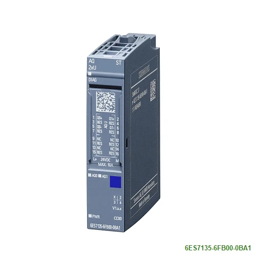
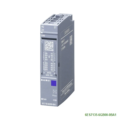
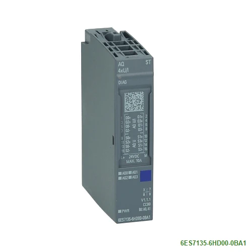
The distributed I/O system ET 200SP offers analog output modules for actuators with current or voltage connection
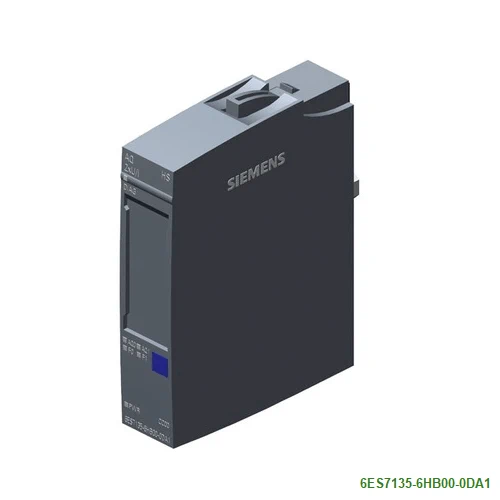
Modules with Standard functionality (ST) are available with 2 or 4 outputs, modules with enhanced functionality (HF High Feature / HS High Speed) always offer 2 outputs.
The High Speed Module AQ 2xUI HS supports fast isochronous outputs and oversampling.
| Article number | 6ES7135-6FB00-0BA1 | 6ES7135-6GB00-0BA1 | 6ES7135-6HD00-0BA1 | 6ES7135-6HB00-0DA1 | 6ES7135-6HB00-0CA1 |
| ET 200SP, AQ 2xU Standard, PU 1 | ET 200SP, AQ 2xI Standard, PU 1 | ET 200SP, AQ 4xU/I ST | ET 200SP, AQ 2 X U/I High Speed | ET 200SP, AQ 2 X U/I High Feature | |
| General information | |||||
| Product type designation | AQ 2xU ST | AQ 2xI ST | AQ 4xU/I ST | AQ 2xU/I HS | AQ 2xU/I HF |
| HW functional status | From FS03 | From FS03 | From FS07 | From FS06 | from FS04 |
| Firmware version | |||||
| ● FW update possible | Yes | Yes | |||
| usable BaseUnits | BU type A0, A1 | BU type A0, A1 | BU type A0, A1 | BU type A0, A1 | BU type A0, A1 |
| Color code for module-specific color identification plate | CC00 | CC00 | CC00 | CC00 | CC00 |
| Product function | |||||
| ● I&M data | Yes; I&M0 to I&M3 | Yes; I&M0 to I&M3 | Yes; I&M0 to I&M3 | Yes; I&M0 to I&M3 | Yes; I&M0 to I&M3 |
| ● Isochronous mode | No | No | No | Yes | Yes |
| ● Output range scalable | No | No | No | ||
| Engineering with | |||||
| ● STEP 7 TIA Portal configurable/integrated from version | V13 SP1 / – | V13 SP1 / – | V11 SP2 / V13 | V13 SP1 | V13 / V13 |
| ● STEP 7 configurable/integrated from version | V5.5 SP3 / – | V5.5 SP3 / – | V5.5 SP3 / – | V5.5 SP3 / – | V5.5 SP3 / – |
| ● PCS 7 configurable/integrated from version | V8.1 SP1 | V8.1 SP1 | |||
| ● PROFIBUS from GSD version/GSD revision | GSD Revision 5 | GSD Revision 5 | One GSD file each, Revision 3 and 5 and higher | GSD Revision 5 | GSD Revision 5 |
| ● PROFINET from GSD version/GSD revision | GSDML V2.3 | GSDML V2.3 | GSDML V2.3 | GSDML V2.3 | GSDML V2.3 |
| Operating mode | |||||
| ● Oversampling | No | No | No | Yes; 2 channels per module | No |
| ● MSO | No | No | No | No | No |
| CiR – Configuration in RUN | |||||
| Reparameterization possible in RUN | Yes | Yes | Yes | Yes | Yes |
| Calibration possible in RUN | No | No | No | No | Yes |
| Supply voltage | |||||
| Rated value (DC) | 24 V | 24 V | 24 V | 24 V | 24 V |
| permissible range, lower limit (DC) | 19.2 V | 19.2 V | 19.2 V | 19.2 V | 19.2 V |
| permissible range, upper limit (DC) | 28.8 V | 28.8 V | 28.8 V | 28.8 V | 28.8 V |
| Reverse polarity protection | Yes | Yes | Yes | Yes | Yes |
| Input current | |||||
| Current consumption (rated value) | 45 mA; without load | 45 mA; without load | |||
| Current consumption, max. | 80 mA | 110 mA | 150 mA | 90 mA; 2 channels current output 20 mA | 90 mA; 2 channels current output 20 mA |
| Power loss | |||||
| Power loss, typ. | 1 W | 1.5 W | 1.5 W | 0.9 W | 0.9 W |
| Address area | |||||
| Address space per module | |||||
| ● Address space per module, max. | 4 byte; + 1 byte for QI information | 4 byte; + 1 byte for QI information | 8 byte; + 1 byte for QI information | 4 byte; + 1 byte for QI information (32 bytes in the oversampling operating mode) | 4 byte; + 1 byte for QI information |
| Hardware configuration | |||||
| Automatic encoding | |||||
| ● Mechanical coding element | Yes | Yes | Yes | Yes | |
| ● Type of mechanical coding element | Type A | Type A | Type A | Type A | Type A |
| Analog outputs | |||||
| Number of analog outputs | 2 | 2 | 4 | 2 | 2 |
| Voltage output, short-circuit protection | Yes | Yes | |||
| Voltage output, short-circuit current, max. | 45 mA | 45 mA | 45 mA | 45 mA | |
| Cycle time (all channels), min. | 1 ms | 1 ms | 5 ms | 125 µs | 750 µs |
| Analog output with oversampling | No | No | No | Yes | |
| ● Values per cycle, max. | 16 | ||||
| ● Resolution, min. | 45 µs; (2 channels), 35 µs (1 channel) | ||||
| Output ranges, voltage | |||||
| ● 0 to 10 V | Yes; 15 bit | Yes; 15 bit | Yes; 15 bit | Yes; 15 bit | |
| ● 1 V to 5 V | Yes; 13 bit | Yes; 13 bit | Yes; 13 bit | Yes; 13 bit | |
| ● -5 V to +5 V | Yes; 15 bit incl. sign | Yes; 15 bit incl. sign | Yes; 15 bit incl. sign | Yes; 15 bit incl. sign | |
| ● -10 V to +10 V | Yes; 16 bit incl. sign | Yes; 16 bit incl. sign | Yes; 16 bit incl. sign | Yes; 16 bit incl. sign | |
| Output ranges, current | |||||
| ● 0 to 20 mA | Yes; 15 bit | Yes; 15 bit | Yes; 15 bit | Yes; 15 bit | |
| ● -20 mA to +20 mA | Yes; 16 bit incl. sign | Yes; 16 bit incl. sign | Yes; 16 bit incl. sign | Yes; 16 bit incl. sign | |
| ● 4 mA to 20 mA | Yes; 14 bit | Yes; 14 bit | Yes; 14 bit | Yes; 14 bit | |
| Connection of actuators | |||||
| ● for voltage output two-wire connection | Yes | Yes | Yes | Yes | |
| ● for voltage output four-wire connection | No | Yes | Yes | Yes | |
| ● for current output two-wire connection | Yes | Yes | Yes | Yes | |
| Load impedance (in rated range of output) | |||||
| ● with voltage outputs, min. | 2 kΩ | 2 kΩ | 2 kΩ | 2 kΩ | |
| ● with voltage outputs, capacitive load, max. | 1 µF | 1 µF | 1 µF | 1 µF | |
| ● with current outputs, max. | 500 Ω | 500 Ω | 500 Ω | 500 Ω | |
| ● with current outputs, inductive load, max. | 1 mH | 1 mH | 1 mH | 1 mH | |
| Destruction limits against externally applied voltages and currents | |||||
| ● Voltages at the outputs | 30 V | 30 V | 30 V | 30 V | 30 V |
| Cable length | |||||
| ● shielded, max. | 200 m | 1 000 m | 1 000 m; 200 m for voltage output | 1 000 m; 200 m for voltage output | 1 000 m; 200 m for voltage output |
| Analog value generation for the outputs | |||||
| Integration and conversion time/resolution per channel | |||||
| ● Resolution with overrange (bit including sign), max. | 16 bit | 16 bit | 16 bit | 16 bit | 16 bit |
| Settling time | |||||
| ● for resistive load | 0.1 ms | 0.1 ms; Typical value | 0.1 ms | 0.05 ms | 0.05 ms |
| ● for capacitive load | 1 ms | 1 ms | 0.05 ms; Max. 47 nF and 20 m cable length | 0.05 ms; Max. 47 nF and 20 m cable length | |
| ● for inductive load | 0.5 ms | 0.5 ms | 0.05 ms | 0.05 ms | |
| Errors/accuracies | |||||
| Output ripple (relative to output range, bandwidth 0 to 50 kHz), (+/-) | 0.02 % | 0.02 % | |||
| Linearity error (relative to output range), (+/-) | 0.03 % | 0.03 % | 0.03 % | 0.03 % | 0.03 % |
| Temperature error (relative to output range), (+/-) | 0.005 %/K | 0.005 %/K | 0.005 %/K | 0.003 %/K | 0.003 %/K |
| Crosstalk between the outputs, min. | -50 dB | -50 dB | -50 dB | ||
| Crosstalk between the outputs, max. | -50 dB | -50 dB | |||
| Repeat accuracy in steady state at 25 °C (relative to output range), (+/-) | 0.05 % | 0.05 % | 0.05 % | 0.03 % | 0.03 % |
| Operational error limit in overall temperature range | |||||
| ● Voltage, relative to output range, (+/-) | 0.5 % | 0.5 % | 0.5 % | 0.2 % | 0.2 % |
| ● Current, relative to output range, (+/-) | 0.5 % | 0.5 % | 0.5 % | 0.2 % | 0.2 % |
| Basic error limit (operational limit at 25 °C) | |||||
| ● Voltage, relative to output range, (+/-) | 0.3 % | 0.3 % | 0.3 % | 0.1 % | 0.1 % |
| ● Current, relative to output range, (+/-) | 0.3 % | 0.3 % | 0.3 % | 0.1 % | 0.1 % |
| Isochronous mode | |||||
| Execution and activation time (TCO), min. | 70 µs | 500 µs | |||
| Bus cycle time (TDP), min. | 125 µs | 750 µs | |||
| Jitter, max. | 5 µs | ||||
| Interrupts/diagnostics/status information | |||||
| Diagnostics function | Yes | Yes | Yes | Yes | Yes |
| Substitute values connectable | Yes | Yes | Yes | Yes | Yes |
| Alarms | |||||
| ● Diagnostic alarm | Yes | Yes | Yes | Yes | Yes |
| Diagnoses | |||||
| ● Monitoring the supply voltage | Yes | Yes | Yes | Yes | Yes |
| ● Wire-break | Yes | Yes | Yes; channel-by-channel, only for output type “current” | Yes; channel-by-channel, only for output type “current” | |
| ● Short-circuit | Yes | Yes | Yes; channel-by-channel, only for output type “voltage” | Yes; channel-by-channel, only for output type “voltage” | |
| ● Group error | Yes | Yes | Yes | Yes | Yes |
| ● Overflow/underflow | Yes | Yes | Yes | Yes | Yes |
| Diagnostics indication LED | |||||
| ● Monitoring of the supply voltage (PWR-LED) | Yes; green PWR LED | Yes; green PWR LED | Yes; green PWR LED | Yes; green PWR LED | Yes; green PWR LED |
| ● Channel status display | Yes; green LED | Yes; green LED | Yes; green LED | Yes; green LED | Yes; green LED |
| ● for channel diagnostics | No | No | No | Yes; red LED | Yes; red LED |
| ● for module diagnostics | Yes; green/red DIAG LED | Yes; green/red DIAG LED | Yes; green/red DIAG LED | Yes; green/red DIAG LED | Yes; green/red DIAG LED |
| Potential separation | |||||
| Potential separation channels | |||||
| ● between the channels | No | No | No | No | No |
| ● between the channels and backplane bus | Yes | Yes | Yes | Yes | Yes |
| ● between the channels and the power supply of the electronics | Yes | Yes | Yes | Yes | Yes |
| Isolation | |||||
| Isolation tested with | 707 V DC (type test) | 707 V DC (type test) | 707 V DC (type test) | 707 V DC (type test) | 707 V DC (type test) |
| Ambient conditions | |||||
| Ambient temperature during operation | |||||
| ● horizontal installation, min. | -30 °C; < 0 °C as of FS03 | -30 °C; < 0 °C as of FS03 | -30 °C; < 0 °C as of FS07 | -30 °C; < 0 °C as of FS06 | -30 °C; < 0 °C as of FS04 |
| ● horizontal installation, max. | 60 °C | 60 °C | 60 °C; Observe derating | 60 °C | 60 °C |
| ● vertical installation, min. | -30 °C; < 0 °C as of FS03 | -30 °C; < 0 °C as of FS03 | -30 °C; < 0 °C as of FS07 | -30 °C; < 0 °C as of FS06 | -30 °C; < 0 °C as of FS04 |
| ● vertical installation, max. | 50 °C | 50 °C | 50 °C; Observe derating | 50 °C | 50 °C |
| Altitude during operation relating to sea level | |||||
| ● Installation altitude above sea level, max. | 5 000 m; Restrictions for installation altitudes > 2 000 m, see manual | 5 000 m; Restrictions for installation altitudes > 2 000 m, see manual | 5 000 m; Restrictions for installation altitudes > 2 000 m, see manual | 5 000 m; Restrictions for installation altitudes > 2 000 m, see manual | 5 000 m; Restrictions for installation altitudes > 2 000 m, see manual |
| Dimensions | |||||
| Width | 15 mm | 15 mm | 15 mm | 15 mm | 15 mm |
| Height | 73 mm | 73 mm | 73 mm | 73 mm | 73 mm |
| Depth | 58 mm | 58 mm | 58 mm | 58 mm | 58 mm |
| Weights | |||||
| Weight, approx. | 31 g | 31 g | 31 g | 31 g | 31 g |