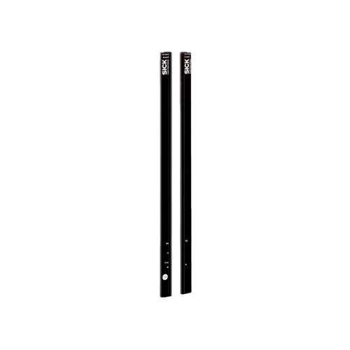
SICK 1213243 SGS4-S140P7TC1W02 PNP Automation Light Grid

USD 1,087.84

36-beam PNP automation light grid with 1,400 mm detection height, 40 mm spacing, 45 mm minimum detectable object, 7 m operating range and M12 connection.

SKU SICK-1213243 Category
SICK Automation Light Grids

SICK SGS4-S140P7TC1W02 PNP Automation Light Grid

BrandSICK
Model IdentifierSGS4-S140P7TC1W02
Official Part Number1213243

Technical Overview

The SICK SGS4-S140P7TC1W02 is a sender/receiver automation light grid with 36 parallel beams at 40 mm spacing and a 1,400 mm detection height. Its 45 mm minimum detectable object supports switching detection across the monitored field. The slim design emits light on the narrow side. It provides 7 m operating range and a 38 ms response in coded parallel-beam operation with a resistive load. Its PNP Q1 output becomes inactive when a beam is interrupted. The selected version has no parameterization. Optical synchronization uses the light beams without a separate synchronization cable. The 24 V DC ±20% device uses PMMA housings and cable connections with M12 four-pin plugs; IP65 protection applies, with an external protective housing required outdoors.

36-beam PNP automation light grid with 1,400 mm detection height, 40 mm spacing, 45 mm minimum detectable object and 7 m operating range.

Key Features

  • 36 parallel beams; 1,400 mm detection height
  • 40 mm beam separation; 45 mm minimum detectable object
  • Slim optical exit; emission on narrow side
  • 7 m operating range; 38 ms, parallel beam coded version, with resistive load
  • PNP Q1; inactive when a light beam is interrupted
  • No parameterization; automatic teach inactive
  • Optical synchronization without a separate synchronization cable
  • 24 V DC ±20%; receiver current ≤70 mA; output maximum 100 mA
  • Cable with M12 four-pin plugs; PMMA housing; without aluminum stabilizer
  • IP65; −25 to +55 °C; external protective housing required outdoors

Monitor opaque product passage across a 1,400 mm field and provide a PNP switching condition to external counting or material-handling logic.

Technical Specification Matrix

ParameterValue
Sensor principleSender/receiver automation light grid
Minimum detectable object45 mm in parallel-beam operation
Beam separation40 mm
Number of beams36
Detection height1,400 mm
Optical light exitSlim; light emission on narrow side
Beam configurationParallel beam active
Operating range7 m
Maximum range10 m; no reserve for environmental effects or diode deterioration
Minimum rangeParallel beam ≥0 m
Response time38 ms, parallel beam coded version, with resistive load
Switching outputPNP Q1; inactive when a light beam is interrupted
ParameterizationNone
Automatic teachInactive
Muting functionDeactivated
Alignment aidWithout alignment aid
Light source950 nm infrared light
Power supply24 V DC ±20%
Receiver current consumption≤70 mA
Maximum output current100 mA
Capacitive output load100 nF
Inductive output load1 H
Initialization time1 s
ConnectionCable with M12 four-pin male connector
Sender pin assignment1=L+; 2=Test; 3=M; 4=not connected
Receiver pin assignmentSingle-PNP diagram: 1=L+; 2=Teach; 3=M; 4=Q1
Input levelsHIGH=10–30 V; LOW=<5 V
Sender inputTest input
Housing materialPMMA
IndicationLED
SynchronizationOptical through the light beams; no separate synchronization cable required
Circuit protectionSupply reverse-polarity protection; Q short-circuit protection; interference-pulse suppression
Protection classIII
IP ratingIP65; outdoor operation only with an external protective housing
Aluminum stabilizerWithout stabilizer
Pulse frequency250 kHz
Operating temperature−25 to +55 °C
Storage temperature−25 to +70 °C
Ambient light immunityDirect sunlight 100,000 lx; indirect 150,000 lx
Shock resistance10 g, 16 ms; DIN EN 60068-2-29
Vibration resistance5 g, 10–55 Hz; IEC 68-2-6
EMCEN 60947-5-2

Industrial Applications

1. Counting separated packages with varying presentation heights

A conveyor can position the sender and receiver across a package path so that the 1,400 mm detection height covers the expected package presentations. External counting logic evaluates Q1 transitions as separated opaque packages interrupt and clear the parallel beams. Setup considers the 45 mm minimum detectable object, 40 mm beam separation, actual package spacing and 38 ms response to create distinct events.

Problem Solved

A detection field spanning the expected package presentations gives external counting logic arrival events across varied heights, helping track separated units at one conveyor position.

Package counting 1,400 mm field PNP Q1

2. Detecting sustained blockage at a discharge chute

A discharge chute can place the light grid across a monitored passage and send Q1 to external timeout logic. Normal product flow creates short interruptions, while a retained opaque item can maintain an interrupted condition beyond the controller’s expected interval. The 7 m operating range supports sender/receiver separation, and timing is set around actual flow conditions and the 38 ms response.

Problem Solved

An interruption-duration signal lets external timeout logic distinguish expected product passage from sustained obstruction, helping identify a developing blockage at the monitored chute section.

Chute blockage External timeout Parallel beams

3. Confirming clearance before a transfer mechanism advances

A transfer station can span the product corridor with the 36 parallel beams and observe Q1 after a load passes through. External sequence logic waits for the monitored path to clear before advancing its next material-handling step. The 1,400 mm detection height covers the defined corridor, with commissioning checking opaque projections against the 45 mm minimum detectable object and the response time.

Problem Solved

A cleared-path condition gives external sequence logic a process reference for the next transfer step, helping avoid advancing material while detectable product projections remain in the corridor.

Transfer clearance External sequencing 36 beams

Select your currency