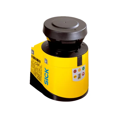
SICK 1056428 S30B-3011CA 3 m S300 Advanced Safety Laser Scanner

USD 4,619.94

S30B-3011CA S300 Advanced provides a 3 m protective field, 270° scan, four triple field sets, PL d/SIL 2 and one OSSD pair; system plug excluded.

SKU SICK-1056428 Category
SICK S300

SICK S30B-3011CA 3 m S300 Advanced Safety Laser Scanner

BrandSICK
Model IdentifierS30B-3011CA
Official Part Number1056428

Technical Overview

The SICK S30B-3011CA is an indoor S300 Advanced safety laser scanner supplied without a system plug. It provides a 3 m protective-field range, an 8 m warning-field range at 15% reflectivity and a separate 30 m distance-measurement range. Its 270° scan supports four triple field sets, twelve fields and four monitoring cases. Configurable resolution spans 30–150 mm in five specified steps, with an 80 ms response specification dependent on basic response time and multiple sampling. One OSSD pair, restart interlock, external device monitoring and static field switching support integration into safety-related control. The Type 3, PL d, SIL 2 scanner uses 24 V DC, CDS configuration and an IP65 aluminum die-cast housing.

Indoor S300 Advanced scanner with 3 m protective range, 270° scan, four monitoring cases, PL d/SIL 2 and one OSSD pair; supplied without system plug.

Key Features

  • S300 Advanced indoor sensor; system plug excluded
  • 3 m protective field; 8 m warning field at 15% reflectivity; separate 30 m distance measurement
  • 270° scan; 0.5° angular resolution
  • Four triple field sets, twelve fields and four monitoring cases
  • Configurable 30, 40, 50, 70 or 150 mm resolution; 80 ms response depends on sampling configuration
  • Type 3, Category 3, PL d and SIL 2; PFHD 8.0 × 10⁻⁸ per hour
  • One OSSD pair, 2 × 250 mA; three programmable diagnostic outputs, 3 × 100 mA
  • Restart interlock, EDM, contour reference, integrated configuration memory and static field switching
  • CDS configuration over RS-232; measured data over RS-422; safe communication via EFI
  • 24 V DC nominal, 16.8–30 V DC range; IP65; operation −10 to +50 °C

Configure indoor protective and warning fields across a 270° scan, with four monitoring cases and an OSSD pair for the safety-related machine stop request.

Technical Specification Matrix

ParameterValue
Product versionS300 Advanced; indoor safety laser scanner
Supplied configurationSensor without system plug
Protective field range3 m
Warning field range8 m at 15% reflectivity
Distance measuring range30 m; separate from protective-field range
Field configurationFour triple field sets; twelve fields
Monitoring cases4
Scanning angle270°
Configurable resolution30 / 40 / 50 / 70 / 150 mm
Angular resolution0.5°
Response time80 ms specification; depends on basic response time and multiple sampling
Protective-field supplement100 mm
Multiple sampling2–16, configurable
Automatic-reset delay2–60 s, configurable
Safety typeType 3; IEC 61496
Safety integrity levelSIL 2; IEC 61508
CategoryCategory 3; EN ISO 13849
Performance levelPL d; EN ISO 13849
PFHD8.0 × 10⁻⁸ per hour
Mission time20 years; EN ISO 13849
Safe state on faultAt least one OSSD in OFF state
Restart interlockProvided
External device monitoringProvided
Monitoring-case switchingProvided
Static protective-field switchingProvided
Contour referenceProvided
Configuration memoryIntegrated
ConnectionSystem plug with or without connecting cable; plug excluded from this sensor
Universal I/OsFive, freely programmable; e.g. EDM/reset input, contamination warning or reset required
EDM and reset inputsOne EDM and one reset/restart input, depending on universal I/O configuration
Static control inputsTwo locally; five with an EFI device such as Flexi Soft or EFI gateway
Standby inputOne
OSSD outputsOne pair; 2 × 250 mA
Diagnostic outputsThree freely programmable application outputs; 3 × 100 mA; e.g. warning field, contamination or reset required
Configuration methodPC with CDS configuration and diagnostic software
Configuration interfaceRS-232; 38.4 kBaud
Measured-data interfaceRS-422; ≤500 kBaud
EFI communicationSafe SICK device communication; ≤500 kBaud; cable ≤50 m, conductor cross-section 0.22 mm²
Protection classIII; EN 50178 and EN 60950
Power supply24 V DC nominal; 16.8–30 V DC
Current consumption0.33 A at 24 V DC without output load; 1.7 A at 24 V DC including maximum output load
Housing materialAluminum die-cast
Housing colorRAL 1021 yellow
Optics coverPolycarbonate; scratch-resistant external coating
IP ratingIP65; EN 60529
Operating temperature−10 to +50 °C
Storage temperature−25 to +50 °C
Vibration resistanceIEC 60068-2-6, IEC 60068-2-64, IEC 60721-3-5, IEC TR 60721-4-5 and IEC 61496-3; Class 5M1
Shock resistanceIEC 60068-2-27, IEC 60721-3-5, IEC TR 60721-4-5 and IEC 61496-3; Class 5M1
Continuous shock50 m/s² for 11 ms; 100 m/s² for 16 ms
Light source905 nm pulsed laser diode
Laser classClass 1; 21 CFR 1040.10/1040.11 and IEC 60825-1
Detectable remission factor1.8% to >1,000% with reflectors
Mounting threadsM5 × 7.5, as shown in scanner drawing
Physical Weight (kg)1.2

Industrial Applications

1. Monitoring an indoor stationary machine approach area

An indoor machine can place the scanner so its configured protective field covers the approach area within the 3 m protective range. The OSSD pair connects to the safety-related control chain for the machine stop request. Field geometry accounts for total stopping time, configured resolution, multiple sampling and the 100 mm protective-field supplement, while restart interlock coordinates the configured restart behavior.

Problem Solved

A configured protective field provides the safety-related controller with an intrusion-dependent stop request, helping monitor the defined approach area through the scanner OSSD pair and restart functions.

3 m protective range OSSD pair Restart interlock

2. Providing an approach warning before protective-field entry

An indoor installation can configure a warning field outside its protective field and use a diagnostic output to signal approach to external indication logic. The warning range is 8 m at 15% reflectivity, separate from the 3 m protective range. The protective field continues to use the OSSD pair for the safety-related stop request, while the warning output supplies the earlier indication.

Problem Solved

Separate warning and protective outputs allow external control to provide an approach indication while retaining the protective-field stop request on the OSSD pair.

Approach indication 8 m warning range Separate outputs

3. Selecting protective fields for different machine operating states

A machine with different operating states can use static control inputs to select among the four configured monitoring cases. Four triple field sets provide twelve fields for the selected layouts. Two static control inputs are available locally, or five with a compatible EFI device. The machine control establishes the correct state selection and field-switch timing before enabling the corresponding movement.

Problem Solved

Configured monitoring cases let the safety-related control use a protective-field layout matched to the selected operating state, helping coordinate detection geometry with the machine sequence.

Four monitoring cases Triple field sets Static control inputs
Select your currency