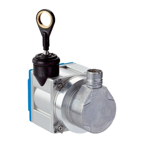
SICK 1034329 PRF08-C1AM0240 TTL Wire Draw Encoder

USD 1,203.02

0–2 m wire draw encoder with TTL / RS-422 output, 10–32 V supply, 0.02 mm rounded resolution, programmable DFS60 encoder and radial M23 connection.

SKU SICK-1034329 Category
SICK HighLine

SICK PRF08-C1AM0240 TTL Wire Draw Encoder

BrandSICK
Model IdentifierPRF08-C1AM0240
Official Part Number1034329

Technical Overview

The SICK PRF08-C1AM0240 combines a DFS60B-S1MA10000 incremental encoder with an MRA-F080-102D2 wire draw mechanism for 0–2 m linear measurement. Its TTL / RS-422 configuration uses a 10–32 V DC supply and a radial M23 twelve-pin male connector. The manufacturer specifies rounded combination resolution of 0.02 mm; mechanism repeatability is ≤1 mm, linearity is ≤±2 mm and hysteresis is ≤2 mm. The 1.35 mm highly flexible stainless steel measuring wire runs against a spring return force of 6–14 N measured at +25 °C. Wire speed is rated at 8 m/s and acceleration at 40 m/s². The mounted mechanism provides IP64, while the encoder provides IP67 with a mating connector fitted. Separate DFS60 programming equipment supports configuration of the documented interface and line-count settings.

0–2 m incremental wire draw encoder with TTL / RS-422 output, 10–32 V DC supply, rounded 0.02 mm combination resolution and radial M23 connection.

Key Features

  • 0–2 m measuring range; 2.2 m actual wire draw length
  • Incremental TTL / RS-422 configuration; 10–32 V DC supply
  • Rounded 0.02 mm wire-draw-plus-encoder resolution
  • Mechanism repeatability ≤1 mm; linearity ≤±2 mm; hysteresis ≤2 mm
  • Mounted DFS60B-S1MA10000 encoder and MRA-F080-102D2 mechanism
  • Programmable encoder; separate DFS60 programming device required
  • 1.35 mm highly flexible V4A stainless steel stranded measuring wire
  • 6–14 N spring return force at +25 °C; 200 mm wire travel per revolution
  • 8 m/s wire speed and 40 m/s² wire acceleration
  • Radial M23 twelve-pin connection; IP64 mechanism; IP67 encoder with mating connector; −30 to +70 °C operation

Convert straight-line wire travel into incremental position signals over a 0–2 m measuring range, with spring return maintaining the measuring-wire take-up.

Technical Specification Matrix

ParameterValue
Measuring range0–2 m
Encoder typeIncremental
Communication interfaceIncremental / TTL / RS-422
Combination resolution0.02 mm, rounded; wire draw mechanism plus encoder
Mechanism repeatability≤1 mm
Mechanism linearity≤±2 mm
Mechanism hysteresis≤2 mm
ProgrammingEncoder is programmable/configurable using separately available DFS60 programming equipment
Factory configurationBuilt-on DFS60 programmed to the specified line count and interface before delivery
Configurable parametersManufacturer lists TTL/HTL electrical interface and up to 10,000 lines; retain the selected product supply range
Power supply10–32 V DC
Power consumption≤0.7 W without load
ConnectionRadial M23 twelve-pin male connector
Mounted encoderDFS60B-S1MA10000, part number 1056866
Mounted wire draw mechanismMRA-F080-102D2, part number 6028625
Measuring wire materialHighly flexible stranded stainless steel 1.4401, V4A
Measuring wire diameter1.35 mm
Measuring wire mass per length7.1 g/m
Mechanism housing materialAnodized aluminum and nickel-plated aluminum die cast
Spring return force6–14 N at +25 °C; may vary at other temperatures
Wire travel per revolution200 mm
Mechanism service lifeTypical 1,000,000 cycles; application-dependent average affected by environment, mounting location, used range, speed and acceleration
Actual wire draw length2.2 m; separate from the 2 m measuring range
Wire acceleration40 m/s²
Wire operating speed8 m/s
IP ratingIP64 mounted mechanism; IP67 encoder with mating connector fitted, IEC 60529
Operating temperature−30 to +70 °C
EMCEN 61000-6-2 and EN 61000-6-3
M23 signal pins6=A complement; 5=A; 1=B complement; 8=B; 4=Z complement; 3=Z; 10=GND; 12=+US; 2/9/11 unassigned
Screen connectionConnected to encoder-side housing; connected to ground at control side
Mechanism mountingTwo M6 holes, 8 mm deep, at 50 mm spacing on each illustrated mounting face
Mechanism body partial size80 mm square; projecting encoder, connector and measuring-wire end are separate extents
MTTFD300 years, EN ISO 13849-1; standard product, not a safety component; nominal component loading, +40 °C average, 8,760 h/year
Physical Weight (kg)1.6

Industrial Applications

1. Tracking a translating carriage over a two-metre stroke

A machine carriage can pull the measuring wire along a straight path as it translates relative to the fixed encoder housing. External incremental electronics relate the resulting signal count to carriage travel after establishing a reference. The installation keeps the wire aligned and evaluates the required position tolerance using mechanism repeatability, linearity and hysteresis separately from the rounded combination resolution.

Problem Solved

Wire travel provides external motion electronics with a displacement reference tied to the moving carriage, helping track relative position across the configured machine stroke.

Carriage displacement 0–2 m Incremental feedback

2. Checking the achieved travel of a reciprocating slide

A reciprocating slide can pull and return the wire during each process cycle. External counting logic compares the measured travel between its start and finish references with the expected stroke to identify incomplete movement. The installed path accounts for the spring return force, direction-dependent hysteresis and application-dependent mechanism life rather than treating resolution as guaranteed stroke accuracy.

Problem Solved

A measured stroke provides external process logic with evidence of achieved travel, helping distinguish a shortened movement from the normal reciprocating slide cycle.

Stroke verification Spring return Travel comparison

3. Monitoring translation rate during a machine traverse

An external monitoring routine can sample successive incremental counts during a straight machine traverse and derive translation rate from the calibrated wire-travel relationship and elapsed time. It compares that rate with the intended motion profile to identify a slow or interrupted movement. Mechanical integration keeps actual wire speed and acceleration within their stated ratings and maintains a controlled wire return.

Problem Solved

Travel counted over time gives external monitoring a translation-rate reference, helping identify a delayed or interrupted traverse using movement of the same measuring wire.

Traverse-rate monitoring External timing Wire motion
Select your currency