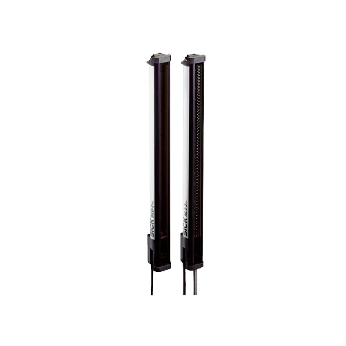
SICK 1214016 MLG10A-0290R10801 290 mm IO-Link Automation Light Grid

USD 2,135.12

MLG-2 Pro light-grid set with 290 mm detection height, 30 beams at 10 mm spacing, 8.5 m operating range, push-pull outputs and IO-Link V1.1.

SKU SICK-1214016 Category
SICK Automation Light Grids

SICK MLG10A-0290R10801 290 mm IO-Link Automation Light Grid

BrandSICK
Model IdentifierMLG10A-0290R10801
Official Part Number1214016

Technical Overview

The SICK MLG10A-0290R10801 is an MLG-2 Pro automation light-grid set with extended functionality, comprising a sender and receiver. Thirty infrared beams at 10 mm separation cover a 290 mm detection height, with an 8.5 m operating range. The minimum detectable object is 10 mm in high-accuracy mode or 14 mm at standard accuracy without cross-beam operation. Cross beam, beam blanking and configurable zones support object evaluation. Four push-pull outputs and IO-Link V1.1 connect results to external control, with Q2/In1 and Q4/In2 sharing input/output connections. The aluminum units use cable synchronization, PMMA front screens and short connector leads. IP65/IP67 protection applies, with an external protective housing required outdoors.

MLG-2 Pro sender/receiver set with 30 beams, 290 mm detection height, 8.5 m operating range, push-pull outputs and IO-Link V1.1.

Key Features

  • MLG-2 Pro extended-function sender/receiver set
  • 30 infrared beams; 10 mm separation; 290 mm detection height
  • 8.5 m operating range; 12 m maximum without environmental/aging reserve
  • 10 mm minimum detectable object in high-accuracy mode; 14 mm standard, without cross beam
  • Cross beam, beam blanking and standard/transparent/dust- and sunlight-resistant modes
  • Four push-pull PNP/NPN outputs; two shared digital-input connections
  • IO-Link V1.1 COM3, 230.4 kbit/s; 32-byte process data; 2.3 ms cycle
  • 3.6 ms response without high-speed operation; initialization <1 s
  • 850 nm infrared LED; cable synchronization; 19.2–28.8 V DC
  • Aluminum housing, PMMA front screen and IP65/IP67; sender, receiver and QuickFix brackets supplied

Evaluate object profiles across a 290 mm beam field and send configured switching conditions or IO-Link data to external inspection control.

Technical Specification Matrix

ParameterValue
Product typeMLG-2 Pro automation light grid; extended functionality
Sensor principleSender/receiver
Beam separation10 mm
Number of beams30
Detection height290 mm
Minimum detectable object10 mm with high measurement accuracy; 14 mm with standard measurement accuracy; depends on beam separation without cross-beam setting
SynchronizationCable
Operating modesStandard; transparent; dust- and sunlight-resistant
FunctionsCross beam; beam blanking; high measurement accuracy
Default configurationQ1=presence detection; Q2/In1=teach input; Q3=presence detection; Q4/In2=presence detection; teach=standard mode
Manufacturer switching applicationsObject detection/width and recognition; height classification; hole detection/size; outside/inside size; object/hole position; zone definition
Manufacturer data-interface applicationsObject and hole detection; object height; outside/inside size; object/hole position
Light source850 nm infrared LED
Operating range8.5 m
Maximum range12 m without reserve for environmental effects and diode deterioration
Minimum range≥0 m
Response time3.6 ms without high-speed operation
Digital outputsFour Q1–Q4; push-pull PNP/NPN
Digital inputsTwo, In1 and In2; shared Q2/In1 and Q4/In2 connections
Output current100 mA
Output loadCapacitive 100 nF; inductive 1 H
IO-LinkV1.1, COM3, 230.4 kbit/s
IO-Link cable limit20 m
IO-Link cycle time2.3 ms
IO-Link identifiersVendorID 26; DeviceID hex 800068 / decimal 8388712
Process data32 bytes, TYPE_2_V; IO-Link V1.0 master uses interleaved TYPE_1_1 process data and TYPE_1_2 on-request data
Power supply19.2–28.8 V DC
Sender current consumption56.5 mA without load at 24 V
Receiver current consumption126 mA without load at 24 V
Ripple<5 Vpp
Initialization time<1 s
Connection leadsSender: M12 five-pin male, 0.22 m; receiver: M12 eight-pin male, 0.27 m and D-coded M12 four-pin female Ethernet connection, 0.19 m
Sender pin assignment1 BN=L+; 2 WH=Sync A; 3 BU=M; 4 BK=TEST; 5 GY=Sync B
Receiver pin assignment1 BN=L+; 2 WH=Sync A; 3 BU=M; 4 BK=Q1/C; 5 GY=Sync B; 6 PK=Q2/In1; 7 VT=Q3; 8 OG=Q4/In2
Ethernet pin assignment1 WH/OG=Tx+; 2 WH/GN=Rx+; 3 OG=Tx−; 4 GN=Rx−
Housing materialAluminum
Front screenPMMA
IndicatorsGreen, yellow and red LEDs
IP ratingIP65 / IP67; outdoor operation requires an external protective housing
Circuit protectionSupply reverse-polarity protection; output Q short-circuit protection; interference pulse suppression
Protection classIII
Operating temperature−30 to +55 °C
Storage temperature−40 to +70 °C
Ambient light immunityDirect 150,000 lx in outdoor mode; indirect 200,000 lx
Shock resistanceContinuous 10 g, 16 ms, 1,000 shocks; single 15 g, 11 ms, three per axis
Vibration resistanceSinusoidal 10–150 Hz, 5 g
EMCEN 60947-5-2
Smart TaskBase logics
UL fileNRKH.E181493
OptionNone
Items suppliedOne sender, one receiver, four QuickFix brackets for this 290 mm detection height, and one Quick Start Guide
Physical Weight (kg)0.849

Industrial Applications

1. Classifying carton height on a conveyor

A conveyor can pass cartons between the sender and receiver with the beam field oriented vertically across the required inspection region. Blocked-beam information supports the manufacturer-listed height-classification function, and configured outputs or IO-Link data report the result to external sorting logic. Commissioning accounts for carton presentation, the 290 mm detection height, beam spacing, selected accuracy mode and transport timing.

Problem Solved

A sampled optical profile gives external sorting logic a carton-height classification reference, helping distinguish configured package groups without fitting a separate sensor at every threshold.

Height classification 30 beams IO-Link

2. Checking an opening in a presented component

An inspection station can present a component so that its intended opening crosses the light-grid field. The documented hole-detection and hole-position functions use received and interrupted beams to form an inspection condition for external control. Setup evaluates the opening geometry against beam separation and the applicable minimum detectable object, while beam blanking excludes defined fixed obstructions from the selected inspection arrangement.

Problem Solved

Configured beam evaluation provides external inspection logic with an opening-related condition, helping identify a missing or misplaced opening in a consistently presented component.

Opening inspection Hole position Beam blanking

3. Monitoring separate material zones at a transfer

A material transfer can divide the optical field into configured zones associated with different portions of the process path. The light grid evaluates object interception across those regions, and configured push-pull outputs supply process conditions to external sequencing. Commissioning establishes zone boundaries and representative loads, uses the documented operating range and response, and assesses actual object geometry and beam coverage.

Problem Solved

Zone-based optical conditions help external transfer logic distinguish where material occupies the monitored field, supporting release and hold decisions for the selected process regions.

Zone occupancy Push-pull outputs Transfer sequencing
Select your currency