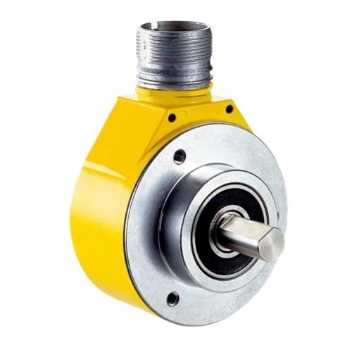
SICK 1069518 DFS60S-S4OA01024 Sin/Cos Safety Encoder

USD 802.36

Sin/Cos safety encoder with 1,024 periods per revolution, 10 mm solid shaft and M23 plug, 4.5–32 V supply and six channels.

SKU SICK-1069518 Category
SICK DFS60S Pro

SICK DFS60S-S4OA01024 Sin/Cos Safety Encoder

BrandSICK
Model IdentifierDFS60S-S4OA01024
Official Part Number1069518

Technical Overview

The SICK DFS60S-S4OA01024 is a DFS60S Pro incremental safety encoder with a 10 mm solid shaft with flat, 19 mm shaft length and face mount flange. It supplies six signal channels through a radial M23 twelve-pin male connector, using a 4.5–32 V DC supply. Sine/cosine signals provide 1,024 periods per revolution and a nominal 1.0 V peak-to-peak differential interface; valid signals are available after 50 ms. The reference pulse is gated with sine and cosine, and its Z signals are excluded from safety operating mode. Safety-related measuring step and accuracy are 0.09° and ±0.09°, separately from the non-safety interpolation example. Its safety data lists SIL 2, SILCL2, PL d and Category 3 subject to the machine configuration and documented diagnostic conditions. Mechanical speed is limited to 9,000 rpm, with self-heating considered within the −30 to +95 °C operating range.

1,024-period Sin/Cos safety encoder with 10 mm solid shaft with flat, 19 mm shaft length and face mount flange, radial M23 twelve-pin male connector and 4.5–32 V DC supply.

Key Features

  • 1,024 sine/cosine periods per revolution; incremental feedback
  • Six channels; nominal 1.0 V peak-to-peak differential Sin/Cos interface
  • 50 ms initialization; ≤153.6 kHz output frequency; ≥120 Ω load resistance
  • Safety-related quadrature step 0.09°; safety-related accuracy ±0.09°
  • SIL 2 / SILCL2 / PL d / Category 3 data subject to machine configuration and diagnostic conditions
  • 10 mm solid shaft with flat, 19 mm shaft length and face mount flange
  • Radial M23 twelve-pin male connector
  • One gated reference pulse; Z and Z complement excluded from safety operating mode
  • 4.5–32 V DC; ≤0.7 W consumption without load; reverse-polarity protection
  • Mechanical speed ≤9,000 rpm; −30 to +95 °C operation with self-heating allowance

Provide 1,024-period differential Sin/Cos feedback for external position and speed measurement, with documented safety-related angle data for drive-system integration.

Technical Specification Matrix

ParameterValue
Communication interfaceIncremental Sin/Cos; nominal 1.0 V peak-to-peak differential
Periods per revolution1,024 sine/cosine periods
Signal channelsSix: COS+, COS−, SIN+, SIN−, Z and Z complement
Initialization time50 ms before valid signals can be read
Output frequency≤153.6 kHz
Load resistance≥120 Ω
Non-safety measuring-step example0.3 arcseconds with e.g. 12-bit interpolation of sine/cosine signals; not safety-related
Integral non-linearityTypical ±45 arcseconds without mechanical tension of stator coupling
Differential non-linearity±7 arcseconds
Safety integrity levelSIL 2, IEC 61508; SILCL2, IEC 62061; manufacturer directs consultation with SICK for exact machine configuration
Performance levelPL d, EN ISO 13849; subject to exact machine configuration
Safety category3, EN ISO 13849
PFH1.7 ×10^-8 per hour; stated at 99% diagnostic coverage achieved by the external drive system and +95 °C operating temperature
Mission time20 years, EN ISO 13849
Safety-related measuring step0.09°, quadrature analysis
Safety-related accuracy±0.09°
Power supply4.5–32 V DC
Power consumption≤0.7 W without load
ConnectionRadial M23 twelve-pin male connector
Reference signalOne; 90 electrical degrees, gated with sine and cosine
Reference-signal restrictionZ and Z complement must not be used for safety operating mode
Reverse-polarity protectionProvided
Protection classIII, DIN EN 61140
Output short-circuit protectionAgainst another channel or GND for maximum 30 s; additionally against supply for maximum 30 s only when supply ≤12 V
Mechanical design10 mm solid shaft with flat, 19 mm shaft length and face mount flange
Shaft materialStainless steel
Flange materialAluminum
Housing materialAluminum die cast
Start-up torque≤0.5 Ncm at +20 °C
Operating torque≤0.3 Ncm at +20 °C
Mechanical operating speed≤9,000 rpm
Self-heatingApproximately 3.0 K per 1,000 rpm; include in permissible operating-temperature assessment
Rotor moment of inertia8 gcm²
Bearing lifetime3.6 ×10^9 revolutions at maximum operating speed and temperature
Angular acceleration≤500,000 rad/s²
IP ratingIP65, IEC 60529; connector arrangement requires plug and mating plug fitted, minimum IP65
Operating temperature−30 to +95 °C with self-heating allowance
Storage temperature−30 to +85 °C without package
Relative humidity90%; condensation not permitted
Shock resistance100 g, 6 ms, EN 60068-2-27; checked with vector-length monitoring
Vibration resistance10 g, 10–1,000 Hz, EN 60068-2-6
EMCEN 61000-6-2; EN 61000-6-3; IEC 61326-3-1
Sin/Cos before differential generationAt 120 Ω load: 0.5 V peak-to-peak ±20%; offset 2.5 V ±10%
Z levels before differential generationAt 120 Ω: LOW 1.75 V ±15%; HIGH 2.90 V ±15%; excluded from safety operating mode
Screen connectionScreen connected to encoder housing; connect to ground at control side
Permissible shaft loading80 N radial; 40 N axial
Product mass basisManufacturer approximate product mass for an encoder with male connector
M23 pin assignment6=COS−; 5=COS+; 1=SIN−; 8=SIN+; 4=Z complement; 3=Z; 10=GND; 12=supply; 2/7/9/11 unassigned
Physical Weight (kg)0.3

Industrial Applications

1. Tracking relative shaft angle with external Sin/Cos electronics

A driven axis can feed the differential sine and cosine signals to external interpolation and counting electronics for relative angular tracking. The 1,024 periods per revolution provide the cyclic signal basis. The system establishes its position reference and treats the non-safety interpolation example separately from the encoder’s stated safety-related measuring step and accuracy when defining the measurement function.

Problem Solved

Differential sine and cosine signals give external motion electronics a continuous cyclic angle reference, helping track relative shaft displacement using the configured interpolation and counting method.

Relative angle Differential Sin/Cos 1,024 periods

2. Observing rotation rate in an external drive monitor

A drive monitor can derive rotation rate from the changing sine and cosine signals and compare it with its intended motion profile. Its input arrangement respects the minimum load resistance and output-frequency rating, while mechanical integration respects speed and self-heating limits. Any safety function uses the documented machine configuration and external diagnostics, including the stated diagnostic-coverage condition for PFH.

Problem Solved

A changing Sin/Cos phase gives external drive monitoring a rotation-rate reference, helping distinguish normal running from a delayed or interrupted motion profile.

Rotation-rate monitoring External diagnostics Drive feedback

3. Synchronizing an ordinary process cycle to the reference pulse

An ordinary process controller can read the gated Z reference event while the shaft rotates and use it to coordinate a once-per-turn process action. The reference is electronically gated with sine and cosine and provides a separate event alongside continuous rotation feedback. This scenario uses Z only for ordinary process synchronization because the manufacturer excludes both Z signals from safety operating mode.

Problem Solved

A separate once-per-turn reference gives ordinary process sequencing a rotational event, helping align a repeated process action with the shaft cycle alongside the Sin/Cos feedback.

Process synchronization Gated reference Ordinary control
Select your currency