USD 40.56 – USD 100.62Price range: USD 40.56 through USD 100.62
| Part Number |
3LD2003-0TK53 |
3LD2103-0TK53 | 3LD2203-0TK53 | 3LD2504-0TK53 | 3LD2704-0TK53 |
| product brand name | SENTRON | SENTRON | SENTRON | SENTRON | SENTRON |
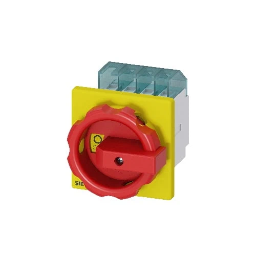
| product designation | 3LD Switch disconnector | 3LD Switch disconnector | 3LD Switch disconnector | 3LD Switch disconnector | 3LD Switch disconnector |
| design of the product | EMERGENCY-STOP switch | EMERGENCY-STOP switch | EMERGENCY-STOP switch | EMERGENCY-STOP switch | EMERGENCY-STOP switch |
| display version for switch position indicator manual operation | 1 ON – 0 OFF | 1 ON – 0 OFF | 1 ON – 0 OFF | 1 ON – 0 OFF | 1 ON – 0 OFF |
| type of switch | front mounted | front mounted | front mounted | front mounted | front mounted |
| design of the actuating element | Short rotary knob | Short rotary knob | Short rotary knob | Short rotary knob | Short rotary knob |
| color of the actuating element | red | red | red | red | red |
| design of handle | rotary operating mechanism, red/yellow | rotary operating mechanism, red/yellow | rotary operating mechanism, red/yellow | rotary operating mechanism, red/yellow | rotary operating mechanism, red/yellow |
| type of the driving mechanism motor drive | No | No | No | No | No |
| General technical data | |||||
| number of poles | 3 | 3 | 3 | 3 | 3 |
| size of switch disconnector | 1 | 2 | 2 | 2 | 4 |
| mechanical service life (operating cycles) typical | 100 000 | 100 000 | 100 000 | 100 000 | 100 000 |
| electrical endurance (operating cycles) | |||||
| ● at AC-23 A at 690 V | 6 000 | 6 000 | 6 000 | 6 000 | 6 000 |
| operating frequency maximum | 50 1/h | 50 1/h | 50 1/h | 50 1/h | 50 1/h |
| degree of pollution | 3 | 3 | 3 | 3 | 3 |
| Voltage | |||||
| insulation voltage rated value | 690 V | 690 V | 690 V | 690 V | 690 V |
| surge voltage resistance rated value | 6 kV | 6 kV | 6 kV | 6 kV | 6 kV |
| operating voltage | |||||
| ● at AC rated value | 690 V | 690 V | 690 V | 690 V | 690 V |
| operating frequency rated value | |||||
| ● minimum | 50 Hz | 50 Hz | 50 Hz | 50 Hz | 50 Hz |
| ● maximum | 60 Hz | 60 Hz | 60 Hz | 60 Hz | 60 Hz |
| Protection class | |||||
| protection class IP | IP65 | IP65 | IP65 | IP65 | IP65 |
| degree of protection NEMA rating | 1, 3R, 4X, 12 | 1, 3R, 4X, 12 | 1, 3R, 4X, 12 | 1, 3R, 4X, 12 | 1, 3R, 4X, 12 |
| protection class IP on the front | IP65 | IP65 | IP65 | IP65 | IP65 |
| Dissipation | |||||
| power loss [W] for rated value of the current at AC in hot operating state per pole | 0.5 W | 1.1 W | 1.8 W | 4.5 W | 7.5 W |
| operational current | |||||
| ● at 40 °C rated value | 16 A | 25 A | 32 A | 63 A | 100 A |
| ● at 45 °C rated value | 16 A | 25 A | 32 A | 63 A | 100 A |
| ● at 50 °C rated value | 16 A | 25 A | 32 A | 63 A | 100 A |
| ● at 55 °C rated value | 16 A | 25 A | 32 A | 63 A | 100 A |
| ● at AC rated value | 16 A | 25 A | 32 A | 63 A | 100 A |
| Main circuit | |||||
| operational current | |||||
| ● at AC-21 at 690 V rated value | 16 A | 25 A | 32 A | 63 A | 100 A |
| ● at AC-21 A at 240 V rated value | 16 A | 25 A | 32 A | 63 A | 100 A |
| ● at AC-21 A at 400 V rated value | 16 A | 25 A | 32 A | 63 A | 100 A |
| ● at AC-21 A at 440 V rated value | 16 A | 25 A | 32 A | 63 A | 100 A |
| ● at AC-23 A at 400 V rated value | 16 A | 20 A | 22 A | 43 A | 70 A |
| operating power | |||||
| ● at AC-23 A at 240 V rated value | 4 kW | 5 kW | 6 kW | 11 kW | 18.5 kW |
| ● at AC-23 A at 400 V rated value | 8 kW | 10 kW | 12 kW | 22 kW | 37 kW |
| ● at AC-23 A at 440 V rated value | 7.5 kW | 9.5 kW | 11.5 kW | 22 kW | 37 kW |
| ● at AC-23 A at 690 V rated value | 8 kW | 10 kW | 12 kW | 19 kW | 30 kW |
| ● at AC-3 at 240 V rated value | 3 kW | 4 kW | 5.5 kW | 11 kW | 18.5 kW |
| ● at AC-3 at 400 V rated value | 6 kW | 8 Kw | 10 kW | 19 kW | 30 kW |
| ● at AC-3 at 690 V rated value | 5.5 kW | 7.5 kW | 9.5 kW | 15 kW | 22 kW |
| Auxiliary circuit | |||||
| number of CO contacts for auxiliary contacts | 0 | 0 | 0 | 0 | 0 |
| number of NC contacts for auxiliary contacts | 0 | 0 | 0 | 0 | 0 |
| number of NO contacts for auxiliary contacts | 0 | 0 | 0 | 0 | 0 |
| operating voltage of auxiliary contacts at AC maximum | 500 V | 500 V | 500 V | 500 V | 500 V |
| continuous current of the auxiliary contact rated value | 10 | 10 | 10 | 10 | 10 |
| insulation voltage of the auxiliary switch rated value | 500 V | 500 V | 500 V | 500 V | 500 V |
| Suitability | |||||
| suitability for use | |||||
| ● main switch | Yes | Yes | Yes | Yes | Yes |
| ● switch disconnector | Yes | Yes | Yes | Yes | Yes |
| ● EMERGENCY OFF switch | Yes | Yes | Yes | Yes | Yes |
| ● safety switch | Yes | Yes | Yes | Yes | Yes |
| ● maintenance/repair switch | Yes | Yes | Yes | Yes | Yes |
| Product details | |||||
| product feature can be locked into OFF position | Yes | Yes | Yes | Yes | Yes |
| accessories | |||||
| product extension optional | |||||
| ● motor drive | No | No | No | No | No |
| ● voltage trigger | No | No | No | No | No |
| number of connectable NC contacts for auxiliary contacts attachable maximum | 3 | 3 | 3 | 3 | 3 |
| number of connectable NO contacts for auxiliary contacts attachable maximum | 3 | 3 | 3 | 3 | 3 |
| number of connectable CO contacts for auxiliary contacts attachable maximum | 0 | 0 | 0 | 0 | 0 |
| number of bracket locks maximum | 3 | 3 | 3 | 3 | 3 |
| hasp thickness of the bracket locks | 4 … 8 mm | 4 … 8 mm | 4 … 8 mm | 4 … 8 mm | 4 … 8 mm |
| Short circuit | |||||
| conditional short-circuit current with line-side fuse protection | |||||
| ● at 690 V by gG fuse rated value | 50 kA | 50 kA | 50 kA | 50 kA | 50 kA |
| let-through current with closed switch | |||||
| ● at 240 V for combination switch + gG fuse maximum | 3 kA | 3.5 kA | 4.5 kA | 6 kA | 10 kA |
| ● at 440 V for combination switch + gG fuse maximum 3 kA | 3 kA | 3.5 kA | 4.5 kA | 6 kA | 10 kA |
| ● at 690 V for combination switch + gG fuse maximum permissible | 3 kA | 4 kA | 5 kA | 6 kA | 10 kA |
| I2t value with closed switch | |||||
| ● at 240 V for combination switch + gG fuse maximum | 2.5 kA2.s | 4 kA2.s | 9 kA2.s | 21 kA2.s | 64 kA2.s |
| ● at 440 V for combination switch + gG fuse maximum | 2.5 kA2.s | 4 kA2.s | 9 kA2.s | 21 kA2.s | 64 kA2.s |
| ● at 690 V for combination switch + gG fuse maximum | 3 kA2.s | 4 kA2.s | 9 kA2.s | 21 kA2.s | 64 kA2.s |
| design of the fuse link | |||||
| ● for short-circuit protection of the main circuit required | fuse gL/gG: 20 A | use gL/gG: 25 A | fuse gL/gG: 40 A | fuse gL/gG: 63 A | fuse gL/gG: 100 A |
| ● for short-circuit protection of the auxiliary switch required | fuse gL/gG: 10 A | fuse gL/gG: 10 A | fuse gL/gG: 10 A | fuse gL/gG: 10 A | fuse gL/gG: 10 A |
| operational current of upstream fuse rated value | 20 A | 25 A | 40 A | 63 A | |
| according UL | |||||
| operational current at AC according to UL 508/UL 60947-4-1 rated value | 16 A | 25 A | 32 A | 63 A | 100 A |
| operating voltage at AC at 50/60 Hz according to UL 508/UL 60947-4-1 rated value | 600 V | 600 V | 600 V | 600 V | 600 V |
| active power [hp] at AC at 480 V according to UL 508/UL 60947-4-1 rated value | 7.5 | 10 | 20 | 40 | 60 |
| active power [hp] at AC at 600 V according to UL 508/UL 60947-4-1 rated value | 10 | 15 | 20 | 50 | 75 |
| short-time withstand current (SCCR) at 600 V according to UL 508/UL 60947-4-1 | 5 Ka | 5 Ka | 5 Ka | 5 Ka | 10 kA |
| continuous current of upstream fuse according to UL rated value | 50 A | 50 A | 80 A | 175 A | 200 A |
| type of fuse according to UL | RK5 | RK5 | RK5 | RK5 | RK5 |
| Connections | |||||
| AWG number as coded connectable conductor cross section solid | |||||
| ● maximum | 10 | 8 | 8 | 6 | 1 |
| ● minimum | 18 | 14 | 14 | 14 | 12 |
| type of connectable conductor cross-sections for copper conductor | |||||
| ● solid | 1x (1…6mm²) | 1x (1,5…16mm²) | 1x (1,5…16mm²) | 1x (2,5…35mm²) | 1x (4…50mm²) |
| ● finely stranded with core end processing | 1x (1…4mm²) | 1x (1,5…10mm²) | 1x (1,5…10mm²) | 1x (2.5…16 mm²) | 1x (4…35mm²) 1x (4…35mm²) 1x (4…35mm²) |
| ● stranded | 1x (1..6mm²) | 1x (1,5…16mm²) | 1x (1,5…16mm²) | 1x (2,5..35mm²) | 1x (4…50mm²) |
| type of connectable conductor cross-sections for auxiliary contacts | |||||
| ● solid | lateral auxiliary switch 2x (0,75 … 2,5mm²), 1x 4mm²; front auxiliary switch 1x (0,75 … 2,5mm²) | lateral auxiliary switch 2x (0,75 … 2,5mm²), 1x 4mm²; front auxiliary switch 1x (0,75 … 2,5mm²) | lateral auxiliary switch 2x (0,75 … 2,5mm²), 1x 4mm²; front auxiliary switch 1x (0,75 … 2,5mm²) | lateral auxiliary switch 2x (0,75 … 2,5mm²), 1x 4mm²; front auxiliary switch 1x (0,75 … 2,5mm²) | lateral auxiliary switch 2x (0,75 … 2,5mm²), 1x 4mm²; front auxiliary switch 1x (0,75 … 2,5mm²) |
| ● finely stranded with core end processing | lateral auxiliary switch 2x (0,75 … 1,5mm²), 1x 2,5mm²; front auxiliary switch 1x 2,5mm² | lateral auxiliary switch 2x (0,75 … 1,5mm²), 1x 2,5mm²; front auxiliary switch 1x 2,5mm² | lateral auxiliary switch 2x (0,75 … 1,5mm²), 1x 2,5mm²; front auxiliary switch 1x 2,5mm² | lateral auxiliary switch 2x (0,75 … 1,5mm²), 1x 2,5mm²; front auxiliary switch 1x 2,5mm² | lateral auxiliary switch 2x (0,75 … 1,5mm²), 1x 2,5mm²; front auxiliary switch 1x 2,5mm² |
| ● stranded | lateral auxiliary switch 2x (0,75 … 2,5mm²), 1x 4mm²; front auxiliary switch 1x (0,75 … 2,5mm²) | lateral auxiliary switch 2x (0,75 … 2,5mm²), 1x 4mm²; front auxiliary switch 1x (0,75 … 2,5mm²) | lateral auxiliary switch 2x (0,75 … 2,5mm²), 1x 4mm²; front auxiliary switch 1x (0,75 … 2,5mm²) | lateral auxiliary switch 2x (0,75 … 2,5mm²), 1x 4mm²; front auxiliary switch 1x (0,75 … 2,5mm²) | lateral auxiliary switch 2x (0,75 … 2,5mm²), 1x 4mm²; front auxiliary switch 1x (0,75 … 2,5mm²) |
| type of electrical connection | |||||
| ● for main current circuit | box terminal | box terminal | box terminal | box terminal | box terminal |
| ● for auxiliary contacts | connection terminals | connection terminals | connection terminals | connection terminals | connection terminals |
| Mechanical Design | |||||
| height | 84 mm | 84 mm | 83 mm | 106 mm | 107 mm |
| width | 67 mm | 67 mm | 67 mm | 90 mm | 90 mm |
| depth | 92.5 mm | 92.5 mm | 92.5 mm | 110.5 mm | 112.5 mm |
| type of device | fixed mounting | fixed mounting | fixed mounting | fixed mounting | fixed mounting |
| fastening method | Built-in unit fixed-mounted version | Built-in unit fixed-mounted version | Built-in unit fixed-mounted version | Built-in unit fixed-mounted version | Built-in unit fixed-mounted version |
| fastening method | |||||
| ● 4-hole front mounting | Yes | Yes | Yes | Yes | Yes |
| ● front mounting with central attachment | No | No | No | No | No |
| ● rail mounting | No | No | No | No | No |
| net weight | 203 g | 187 g | 205 g | 420 g | 497 g |
| Environmental conditions | |||||
| ambient temperature during operation | |||||
| ● minimum | -25 °C | -25 °C | -25 °C | -25 °C | -25 °C |
| ● maximum | 55 °C | 55 °C | 55 °C | 55 °C | 55 °C |
| ambient temperature during storage | |||||
| ● minimum | -25 °C | -25 °C | -25 °C | -25 °C | -25 °C |
| ● maximum | 55 °C | 55 °C | 55 °C | 55 °C | 55 °C |