USD 576.16
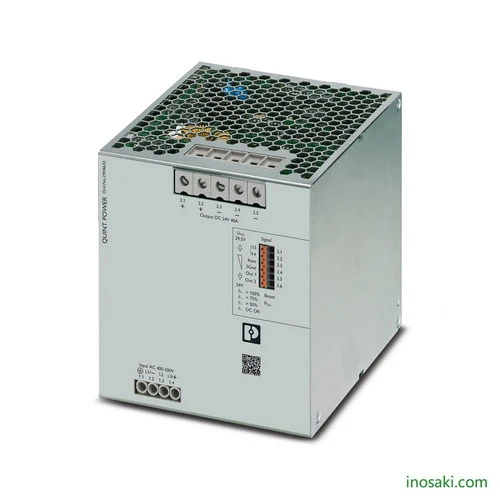
High-performance Phoenix Contact QUINT4-PS/3AC/24DC/40 power supply, 24V DC 40A output with SFB, surge protection, and preventive monitoring.
The Phoenix Contact QUINT4-PS/3AC/24DC/40 is a powerful industrial power supply delivering 24 V DC at 40 A, designed to keep critical systems running without interruption. Built with advanced selective fuse breaking (SFB) technology, it ensures fast tripping of standard protective devices and dependable startup of demanding loads. Its NFC interface allows flexible configuration of signaling thresholds and output behavior. Combined with built-in surge protection and intelligent monitoring, this device significantly improves uptime and protects sensitive automation equipment, making it a reliable choice for industries that cannot afford power instability.
Engineered for maximum availability, the QUINT4-PS/3AC/24DC/40 provides more than just a stable DC output. Its preventive monitoring alerts users to critical operating states early, helping avoid costly downtime. With static and dynamic boost functions, it can temporarily deliver higher output to handle peak loads or expand systems easily. The integrated surge arrester provides strong immunity against electrical disturbances, while its compact DIN rail design makes installation straightforward. This combination of performance and resilience ensures dependable operation in production facilities, rail systems, process plants, and other environments where uninterrupted power is vital.
The QUINT4-PS/3AC/24DC/40 is built for industries where uninterrupted performance is non-negotiable. With its 40 A output, NFC configurability, and advanced SFB technology, it offers unmatched system reliability. It doesn’t just power your equipment—it empowers your entire operation by ensuring heavy loads start safely, signaling issues before failure, and adapting seamlessly to future expansion.
Unstable power, hidden failures, and overloaded circuits are common headaches in automation systems. The QUINT4-PS/3AC/24DC/40 solves these challenges by combining preventive monitoring, surge protection, and boost capabilities. It eliminates downtime risks, trips breakers in milliseconds to protect circuits, and keeps operations running smoothly—even during demanding peak loads or sudden voltage disturbances.
| Feature | Details | Benefit |
|---|---|---|
| Output Voltage | 24 V DC (adjustable up to 29.5 V DC) | Flexible voltage setting for diverse applications |
| Output Current | 40 A nominal, 45 A static boost, 60 A dynamic boost | Handles heavy startup loads and short-term peak demands |
| SFB Technology | Delivers up to 215 A for 15 ms | Trips standard breakers within milliseconds for maximum circuit protection |
| Efficiency | Up to 95.7% | Reduces energy loss and lowers operating costs |
| Input Voltage Range | 3-phase 400–500 V AC / ±260–300 V DC | Wide range ensures compatibility with global industrial grids |
| Surge Protection | Integrated gas-filled arrester, up to 6 kV | Superior immunity against power disturbances |
| Preventive Function Monitoring | Early warning of critical states | Reduces downtime through proactive maintenance |
| Connection Options | Parallel or series operation | Enables redundancy and system scalability |
| Mounting | DIN rail NS 35, horizontal | Easy installation into control cabinets |
| Approvals | UL, CSA, DNV, BV, ABS, SEMI F47 | Certified for global industrial and marine applications |
| Operating Temperature | -25 °C to +70 °C (derating above 60 °C) | Reliable performance in harsh environments |
| Protection Class | IP20, Class I | Safe and compliant for industrial use |
Download Phoenix Contact QUINT4-PS/3AC/24DC/40 (2904623) Datasheet
| Commercial Attribute | Details |
|---|---|
| GTIN Number | 4055626356105 |
| Tariff Number | 85044095 |
| Weight (Net / With Packing) | 2,422 g / 2,811.6 g |
| Country of Origin | Thailand (TH) |
Modern substations rely on stable control voltages for protection relays to function during faults or switching events. The QUINT4-PS ensures uninterrupted relay operation through its strong surge protection and rapid SFB response. Preventive monitoring gives early alerts of irregular conditions, allowing timely maintenance. Its dynamic boost capability handles sudden current demands, keeping protective equipment reliable even when grid conditions fluctuate.
Automated manufacturing lines often require high bursts of current when motors and actuators first engage. The QUINT4-PS supplies these short surges through its boost functions without dropping system voltage. If a circuit fault occurs, the SFB feature trips only the affected breaker, preventing unnecessary downtime. This means production continues smoothly, protecting valuable equipment and avoiding costly interruptions.
In data centers, backup power must remain reliable for systems such as fire protection, UPS controls, and communication lines. The QUINT4-PS supports parallel operation, enabling redundant supply configurations for maximum availability. Preventive function monitoring highlights performance changes before failure, reducing risks of unexpected outages. With its efficiency and flexible input range, it also helps operators lower energy use while maintaining uninterrupted service.
Railway signaling equipment must endure extreme climates, vibrations, and sudden surges. The QUINT4-PS is engineered to withstand these harsh conditions, operating reliably from sub-zero cold to high heat. Its integrated surge protection resists transient spikes, while SFB technology isolates local faults to keep unaffected signaling zones active. The NFC configuration allows quick adjustments on-site, ensuring smooth operation in demanding railway networks.
| Category | Part Number | Description | Benefit |
|---|---|---|---|
| Mounting Accessories | 2938235 | UWA 182/52 Universal Wall Adapter | Provides secure mounting in environments with strong vibrations |
| 2901664 | UWA 130 2-piece Wall Adapter | Ensures reliable installation on side profiles for vibration resistance | |
| Programming Adapter | 2909681 | TWN4 MIFARE NFC USB Adapter | Enables easy NFC configuration of QUINT4-PS units |
| Fuse | 3061318 | 10.3×38 mm Fuse, 6A PV | High-voltage DC protection for safe operation |
| Surge Protection | 2905230 | PLT-SEC-T3-3S-230-FM | Type 3 surge protection for 3-phase power supply networks |
| 2907925 | PLT-SEC-T3-24-FM-PT | Type 3 surge protection for 24 V AC/DC single-phase networks | |
| 2907916 | PLT-SEC-T3-24-FM-UT | Surge protection with integrated status indicator and remote signaling | |
| Circuit Breaker | 2906031 | CBMC E4 24DC/1-4A NO | Multi-channel electronic circuit breaker, 4 loads |
| 2906032 | CBMC E4 24DC/1-10A NO | Multi-channel circuit breaker for 24 V DC loads up to 10 A | |
| 2910410 | CBMC E4 24DC/1-4A+ IOL | Circuit breaker with IO-Link interface for advanced diagnostics | |
| 2910411 | CBMC E4 24DC/1-10A IOL | IO-Link circuit breaker, 10 A channels for smart monitoring | |
| 2905743 | CBM E4 24DC/0.5-10A NO-R | Multi-channel breaker with active current limitation | |
| 2905744 | CBM E8 24DC/0.5-10A NO-R | Eight-channel electronic circuit breaker for higher load distribution | |
| End Bracket | 1201662 | E/AL-NS 35 End Clamp | Provides secure support on DIN rails |
For expert guidance before placing your order.
Warranty – 1-year warranty for your peace of mind.
Global Shipping – We ship worldwide with secure packaging and reliable delivery.
Technical Support – Contact us for professional after-sales technical assistance.