USD 632.58
Reliable Phoenix Contact QUINT4 40A power supply with NFC, fuse breaking, surge protection, and high efficiency for demanding industrial systems.
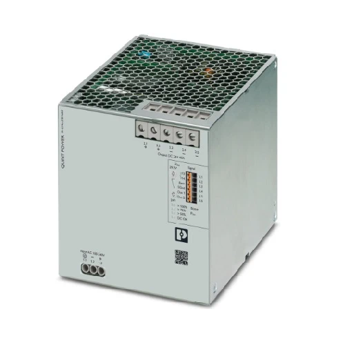
The Phoenix Contact QUINT4-PS/1AC/24DC/40 is a single-phase industrial power supply built to deliver 24 V DC at 40 A with exceptional stability. It is engineered with advanced fuse-breaking technology, configurable output characteristics, and an NFC interface for easy customization. The design includes strong surge protection and a wide input range, making it resilient against harsh grid conditions. Preventive monitoring functions provide early alerts before critical issues arise, helping maintain uninterrupted system performance. Compact DIN-rail installation and outstanding load management make this unit an ideal choice for demanding automation and control applications.
This 40 A QUINT4 series power supply combines efficiency, reliability, and intelligence to optimize uptime. With energy efficiency near 96%, it minimizes power losses while delivering stable output. The dynamic boost capability allows it to supply up to 60 A for short periods, supporting the reliable start-up of heavy loads. Its preventive diagnostics reduce unexpected downtime by alerting operators to irregularities early. The unit can be tailored via NFC programming, ensuring flexibility across various installations. Designed to operate in extreme conditions from -25 °C to +70 °C and certified for international standards, it provides long-term safety and consistent performance in mission-critical systems.
The QUINT4-PS/1AC/24DC/40 stands out for its ability to deliver a steady 24 V DC at 40 A while adapting to dynamic industrial demands. With smart NFC configuration, robust surge protection, and powerful boost reserves, it ensures both flexibility and resilience. It’s not just a power supply—it’s a reliability safeguard designed for mission-critical environments.
Unstable power, unexpected downtime, and difficult load start-ups are common challenges in automation. The QUINT4-PS/1AC/24DC/40 solves these by offering selective fuse breaking, dynamic boost for heavy loads, and preventive monitoring that detects issues before they disrupt operations. It transforms power management into a proactive advantage, ensuring smooth, continuous performance.
| Feature | Details | Benefit |
|---|---|---|
| Input Voltage Range | 100–240 V AC / 110–250 V DC | Flexible operation across global grids |
| Output Voltage / Current | 24 V DC / 40 A | High power capacity for demanding loads |
| Efficiency | Up to 95.9% | Energy savings and reduced heat generation |
| Dynamic Boost | Up to 60 A (5 s) | Ensures reliable start-up of heavy loads |
| Selective Fuse Breaking | 215 A (15 ms) | Trips standard circuit breakers quickly and safely |
| Surge Protection | Integrated up to 6 kV | Enhanced resilience against grid disturbances |
| Preventive Monitoring | Configurable signaling & diagnostics | Detects issues before failures occur |
| NFC Configuration | Programmable thresholds & settings | Easy customization without complex wiring |
| Operating Temperature | -25 °C to +70 °C | Reliable performance in harsh environments |
| Mounting | DIN rail NS 35 | Standardized, simple installation |
| Approvals | UL, CSA, DNV GL, SEMI F47 | Certified for global industrial use |
Download QUINT4-PS/1AC/24DC/40 (Article No. 2904603) Datasheet
| Commercial Attribute | Details |
|---|---|
| GTIN (EAN) | 4055626355092 |
| Customs Tariff Number | 85044095 |
| Weight (Net / with Packing) | 2,887 g / 3,250 g |
| Country of Origin | Thailand (TH) |
In fast-paced production facilities, conveyor systems and robotic arms often draw heavy inrush currents during start-up. Conventional power supplies may struggle, causing nuisance trips or downtime. The QUINT4-PS/1AC/24DC/40 solves this with its dynamic boost function, delivering up to 60 A for short periods to support heavy loads. Its Selective Fuse Breaking technology ensures that only the affected circuit disconnects during a fault, while the rest of the line continues operating. This prevents unnecessary halts, improves uptime, and keeps the entire manufacturing line running smoothly.
Remote energy platforms and mining sites experience harsh electrical disturbances, from voltage fluctuations to strong transients. The QUINT4-PS/1AC/24DC/40 is designed with robust surge protection up to 6 kV and maintains reliable performance across wide AC and DC input ranges. When grid conditions become unstable, its built-in buffer continues supplying loads, while preventive monitoring signals operators of irregularities before they escalate. This level of resilience makes it ideal for critical safety and control systems in energy exploration and extraction environments.
Modern logistics depends on AGVs for precise material handling, but these vehicles require dependable 24 V DC power to keep sensors, drives, and communication modules stable. The QUINT4-PS/1AC/24DC/40 provides the necessary consistency, even under variable battery or line conditions. Its NFC configuration feature allows engineers to fine-tune signaling thresholds, ensuring smooth integration in compact control cabinets. Preventive monitoring helps operators detect potential failures early, reducing unplanned downtime and keeping fleets of AGVs working continuously in warehouses and production halls.
Marine automation demands equipment that can tolerate fluctuating supply conditions while safeguarding essential systems. The QUINT4-PS/1AC/24DC/40 offers adjustable output to compensate for voltage drops across long cables, ensuring stable 24 V delivery to navigation, lighting, and alarm systems. Its fuse-breaking function isolates faults locally, preventing a single issue from spreading through the ship’s power network. Built for rigorous environments, it provides peace of mind for ship operators who rely on uninterrupted operation of critical onboard systems.
| Category | Product Name | Part Number | Description |
|---|---|---|---|
| Mounting Accessories | UWA 182/52 Mounting Adapter | 2938235 | Universal wall adapter for secure mounting in high-vibration environments. |
| UWA 130 Mounting Adapter | 2901664 | Two-piece wall adapter, side-mounted, for reliable installation under vibration. | |
| Programming Tools | TWN4 MIFARE NFC USB Adapter | 2909681 | NFC programming adapter with USB interface for easy configuration of QUINT power supplies. |
| Surge Protection Devices | PLT-SEC-T3-230-FM-UT | 2907919 | Type 2/3 surge protection for 230 V AC/DC networks with remote signaling. |
| PLT-SEC-T3-24-FM-UT | 2907916 | Type 3 surge protection for 24 V AC/DC networks with integrated status indicator. | |
| DIN Rail Accessories | E/AL-NS 35 End Bracket | 1201662 | End clamp for securing devices on DIN rail NS 35. |
| Electronic Circuit Breakers | CBMC E4 24DC/1-4A NO | 2906031 | Multi-channel electronic circuit breaker for four 24 V DC loads, 1–4 A protection. |
| CBMC E4 24DC/1-10A NO | 2906032 | Multi-channel breaker for four 24 V DC loads, adjustable 1–10 A. | |
| CBMC E4 24DC/1-4A+ IOL | 2910410 | Multi-channel breaker with IO-Link interface, 1–4 A range. | |
| CBMC E4 24DC/1-10A IOL | 2910411 | Multi-channel breaker with IO-Link interface, adjustable 1–10 A. | |
| CBM E4 24DC/0.5-10A NO-R | 2905743 | Multi-channel breaker with active current limitation, four load channels. | |
| CBM E8 24DC/0.5-10A NO-R | 2905744 | Multi-channel breaker with active current limitation, eight load channels. |
For expert guidance before placing your order.
Warranty – 1-year warranty for your peace of mind.
Global Shipping – We ship worldwide with secure packaging and reliable delivery.
Technical Support – Contact us for professional after-sales technical assistance.