USD 212.94
Phoenix Contact QUINT4-PS/1AC/12DC/7.5/PT: 12V 7.5A with Dynamic Boost, preventive monitoring, high efficiency, and 45 mm DIN-rail design for reliable uptime.
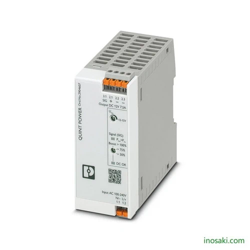
The Phoenix Contact QUINT4-PS/1AC/12DC/7.5/PT power supply (Article No. 2904607) is engineered to deliver stable 12 V DC at 7.5 A, ensuring reliability in demanding automation environments. With a compact housing only 45 mm wide, it optimizes cabinet space while supporting heavy load start-ups through its integrated dynamic boost function. The unit achieves high efficiency above 92%, minimizing energy loss and heat buildup. Featuring push-in connection technology for quick installation, it provides robust performance and preventive function monitoring, helping engineers maintain uninterrupted operation in critical control applications.
The QUINT4-PS/1AC/12DC/7.5/PT is built to go beyond conventional power supplies by offering preventive monitoring that identifies irregularities before they lead to system downtime. Its temporary power reserve enables secure starting of high inrush current loads, reducing the risk of failures in industrial machinery. With its slim profile, it fits seamlessly into tight control cabinets, saving space for other essential components. High conversion efficiency lowers operating costs and extends equipment service life. Whether in manufacturing plants, process control, or transport systems, this supply ensures consistent, dependable power delivery that safeguards sensitive electronics and boosts overall productivity.
Because it transforms a compact 45 mm housing into a powerhouse of reliability, offering dynamic boost for heavy loads, preventive monitoring to anticipate failures, and effortless push-in installation. This means engineers get more uptime, more efficiency, and more space in their control cabinets—all from a power supply that’s built to perform where reliability truly matters.
It solves the hidden but costly challenge of unstable or unreliable DC power in industrial systems. Sudden inrush currents, heat buildup, and unnoticed faults often cause downtime—this supply eliminates those risks. With early diagnostics, high efficiency, and the muscle to start heavy loads, it ensures continuous operation while protecting sensitive electronics from disruption.
| Feature | Details | Benefit |
|---|---|---|
| Input Voltage Range | 100–240 V AC / 110–250 V DC | Flexible use across global grids and DC systems |
| Output Voltage / Current | 12 V DC / 7.5 A | Reliable power for sensitive industrial devices |
| Dynamic Boost | Up to 12.75 A for 5 seconds | Starts heavy loads without risk of failure |
| Efficiency | Up to 92.5% | Lower heat generation and reduced energy costs |
| Preventive Function Monitoring | LED signaling for load and voltage states | Early detection of faults prevents downtime |
| Housing Width | 45 mm (DIN rail mount) | Saves valuable space in control cabinets |
| Connection Type | Push-in terminals | Faster, tool-free installation |
| Protection Features | Short-circuit proof, overload, overvoltage protection | Enhanced safety and long service life |
| Operating Temperature | -25 °C to +70 °C | Reliable performance in harsh environments |
| Certifications | UL Listed, CE, IEC, DNV, BV | Compliance with international standards |
| Life Expectancy | >280,000 h at 25 °C | Long service time, reduced maintenance |
| Enclosure | Plastic housing, IP20 rated | Durable design with basic protection |
| Commercial Data | Details |
|---|---|
| GTIN Number | 4055626255767 |
| Tariff Number | 85044095 |
| Weight (Net) | 307 g |
| Weight (With Packaging) | 384.6 g |
| Country of Origin | Vietnam |
Modern rail networks rely on distributed signal boxes that must operate in harsh outdoor conditions. This power supply’s compact 45 mm width makes it ideal for crowded control cabinets along the tracks. Its dynamic boost ensures that signaling equipment starts reliably despite sudden current demands. Preventive monitoring adds another layer of safety by alerting operators to irregular conditions early, which is essential in critical transport infrastructure where uptime cannot be compromised.
Energy storage units require dependable low-voltage power for their control and safety circuits. The QUINT4-PS/1AC/12DC/7.5/PT provides a constant 12 V DC while handling occasional spikes in load during balancing or startup cycles. Its high efficiency minimizes energy waste, which is especially valuable in systems designed to maximize renewable energy usage. Preventive diagnostics help keep the storage system operating smoothly and reduce costly maintenance interruptions.
Automation racks with dozens of I/O modules and relays depend on consistent power distribution. This unit delivers 7.5 A at 12 V with excellent voltage stability, ensuring sensors and controllers function without disruption. Push-in terminals shorten installation time and reduce wiring errors, while the slim housing leaves more room for additional equipment. Built-in monitoring and protection features reduce the risk of unexpected downtime in production lines where reliability translates directly into productivity.
In remote microgrids combining solar, wind, or battery systems, space-saving and efficient power supplies are vital. This device supports stable 12 V DC power to controllers, sensors, and communication units while consuming minimal energy itself. Dynamic boost assists in handling sudden startup demands from connected devices, and diagnostic feedback helps operators maintain reliability even in areas without immediate technical support. Its robust design makes it well suited for off-grid or decentralized energy projects.
| Category | Model | Article No. | Description & Benefit |
|---|---|---|---|
| Surge Protection | PLT-SEC-T3-230-FM-UT | 2907919 | Type 2/3 surge protection for 230 V AC/DC, shields power supply against voltage spikes. |
| Surge Protection | PLT-SEC-T3-24-FM-UT | 2907916 | Type 3 surge protection for 24 V AC/DC, safeguards sensitive connected devices. |
| Electronic Circuit Breaker | PTCB E1 24DC/0.63A SI-R | 1464485 | Single-channel breaker, 0.63 A fixed, with remote signaling/reset for DC loads. |
| Electronic Circuit Breaker | PTCB E1 24DC/0.63A NO | 1464486 | Compact protection breaker, 0.63 A fixed, with active current limitation. |
| Electronic Circuit Breaker | PTCB E1 24DC/0.1–0.63A NO | 1441495 | Adjustable breaker 0.1–0.63 A, protects sensitive equipment from overloads. |
| Electronic Circuit Breaker | PTCB E1 24DC/0.1–0.63A SI-R | 1441496 | Adjustable breaker with remote reset/signaling, flexible DC load protection. |
| Tools | SF-SL 0,4X2,0-60 | 1212546 | Precision screwdriver for wiring terminals, ergonomic non-slip grip. |
| Complementary Power Supply | QUINT4-PS/1AC/24DC/5 | 2904603 | 24 V DC / 5 A QUINT4 supply, same family with higher voltage output. |
For expert guidance before placing your order.
Warranty – 1-year warranty for your peace of mind.
Global Shipping – We ship worldwide with secure packaging and reliable delivery.
Technical Support – Contact us for professional after-sales technical assistance.