USD 359.32
Reliable 24V DC 5A power supply with SFB technology, POWER BOOST, and protective coating. Ensures uptime and safety in demanding industrial systems.
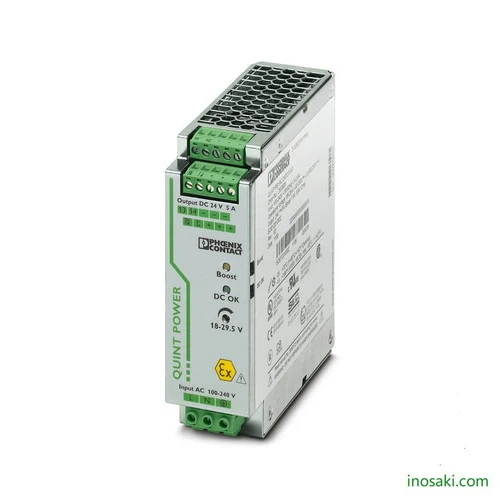
The Phoenix Contact QUINT-PS/1AC/24DC/5CO power supply is a high-performance 24 V DC / 5 A unit engineered for demanding industrial applications. Featuring advanced Selective Fuse Breaking (SFB) technology, it ensures fast and reliable tripping of circuit breakers, protecting connected equipment from costly failures. Its adjustable output voltage range of 18 to 29.5 V DC offers adaptability across various systems, while the protective coating safeguards against moisture and harsh conditions. Compact, DIN-rail mounted, and optimized for efficiency, this power supply is ideal for keeping automation and control processes running with maximum stability.
The QUINT-PS/1AC/24DC/5CO power supply is designed for industries where uptime and resilience are critical. It provides a POWER BOOST reserve delivering up to 1.5 times the rated current, ensuring dependable start-up of heavy loads without interruptions. Its preventive monitoring continuously checks operating status, alerting users to potential issues before they become failures. Built for environments such as manufacturing, transportation, and energy systems, it carries multiple industry approvals for safe global deployment. With its protective coating and high efficiency, this model reduces downtime, lowers maintenance needs, and extends equipment lifespan, making it a reliable solution for mission-critical operations.
The Phoenix Contact QUINT-PS/1AC/24DC/5CO stands out because it combines high reliability, protective coating, and advanced features like SFB technology and POWER BOOST reserve. Unlike standard power supplies, it ensures equipment runs smoothly even under tough startup conditions or heavy loads. Its preventive monitoring provides early alerts, reducing downtime and maintenance costs. This makes it more than just a power source—it’s a safeguard for productivity and long-term system availability.
In industrial environments, power fluctuations, moisture, and heavy load demands often cause unexpected equipment failures. The QUINT-PS/1AC/24DC/5CO solves this by offering fast breaker tripping, reliable surge handling, and extra current reserves to power difficult loads. Its protective coating shields against humidity and harsh conditions, while predictive monitoring alerts operators before breakdowns occur. This means fewer disruptions, greater energy efficiency, and a dependable power foundation for mission-critical automation systems.
| Feature | Details | Benefit |
|---|---|---|
| Output Voltage | 24 V DC (adjustable 18–29.5 V DC) | Flexible integration across multiple industrial systems |
| Output Current | 5 A nominal, 7.5 A POWER BOOST | Reliable startup of heavy loads and peak demand handling |
| SFB Technology | Delivers up to 6× nominal current (12 ms) | Fast tripping of standard breakers, improved protection |
| Preventive Monitoring | Early warning of critical states | Prevents unplanned downtime and enhances reliability |
| Protective Coating | Resistant to 100% humidity | Ensures long service life in harsh environments |
| Efficiency | Up to 90% (230 V AC input) | Lower energy losses and reduced operational costs |
| Input Voltage Range | 85–264 V AC / 90–410 V DC | Wide compatibility with global power systems |
| Power Output | 120 W rated | Stable and consistent power for automation equipment |
| Parallel/Series Operation | Supported | Enables redundancy and capacity scaling |
| DIN Rail Mounting | Compact 40 × 130 × 125 mm | Space-saving and easy installation |
| Approvals & Compliance | UL, ATEX, IECEx, SEMI F47, EN 45545-2 HL3 | Certified for use in global, rail, and hazardous environments |
| Ambient Temperature | –40 °C to +70 °C | Reliable operation in extreme conditions |
| Signal Interfaces | DC OK & POWER BOOST outputs | Simple integration with monitoring systems |
Download QUINT-PS/1AC/24DC/5CO (2320908) Datasheet
| Commercial Attribute | Details |
|---|---|
| GTIN (EAN/UPC) | 4046356520010 |
| Customs Tariff Number (HS Code) | 85044095 |
| Weight (incl. packing) | 1,081.3 g |
| Weight (net, excl. packing) | 777 g |
| Country of Origin | Thailand (TH) |
In food and beverage production, electrical systems often operate in humid, washdown-prone environments where condensation and moisture can damage electronics. The QUINT-PS/1AC/24DC/5CO is coated for protection, ensuring consistent performance even at 100% humidity. Its POWER BOOST function supplies extra current to start conveyors, pumps, and motors without voltage dips. Preventive monitoring alerts operators early if loads or supply conditions shift, reducing the risk of unexpected stoppages. This makes it a trusted choice for continuous packaging, bottling, and quality control systems that require reliable 24 V power around the clock.
Traffic management cabinets are exposed to temperature extremes, dust, and electrical disturbances that can disrupt operations. The QUINT-PS/1AC/24DC/5CO is designed to withstand –40 °C to +70 °C, making it ideal for roadside and outdoor installations. Its Selective Fuse Breaking (SFB) technology delivers short bursts of high current to quickly isolate faulty circuits, while keeping the rest of the system powered. This ensures signals, controllers, and sensors remain active during faults, minimizing downtime and increasing safety on the road. By combining ruggedness with diagnostic functions, the supply keeps urban infrastructure running smoothly.
Remote oil and gas sites demand power equipment that can survive harsh, corrosive, and unstable environments. The QUINT-PS/1AC/24DC/5CO addresses this challenge with protective coating, shock resistance, and buffering against short power interruptions. Its preventive monitoring functions provide early warnings of overloads or voltage irregularities, enabling maintenance teams to act before failures occur. POWER BOOST ensures even heavy pumps and control modules start reliably under demanding conditions. This dependable performance reduces costly shutdowns and keeps operations safe and compliant, even in remote locations where immediate service is not possible.
Modern machine builders need scalable, reliable power solutions that adapt to different configurations. The QUINT-PS/1AC/24DC/5CO supports both parallel and series operation, allowing redundancy or higher capacity when required. Its adjustable output voltage compensates for cable losses in larger installations, ensuring stable 24 V delivery at every device. The fast-response SFB technology quickly trips only the affected branch during a fault, protecting the rest of the system from disruption. With these features, manufacturers can design modular machinery with maximum uptime, simplified integration, and higher productivity for industrial automation lines.
| Category | Model Name | Article Number | Benefit / Usage |
|---|---|---|---|
| Mounting Adapter | UTA 107/30 | 2320089 | Universal DIN rail adapter for flexible mounting options. |
| Mounting Adapter | UWA 182/52 | 2938235 | Wall adapter for stable installation under heavy vibration. |
| Mounting Adapter | QUINT-PS-ADAPTERS7/1 | 2938196 | Enables mounting of QUINT power supplies on Siemens S7-300 rails. |
| Cooling Accessory | QUINT-PS/FAN/4 | 2320076 | Fan module for enhanced cooling at high ambient temperatures. |
| Redundancy Module | QUINT-DIODE/12-24DC/2X20/1X40 | 2320157 | Ensures uniform redundancy and higher reliability for dual supply systems. |
| Redundancy Module | QUINT-ORING/24DC/2X10/1X20 (with coating) | 2320173 | Active redundancy with Auto Current Balancing (ACB) and monitoring. |
| Redundancy Module | TRIO-DIODE/12-24DC/2X10/1X20 | 2866514 | Compact diode module for redundancy in smaller installations. |
| Circuit Breaker | CB TM1 1A SFB P | 2800836 | Thermal-magnetic breaker with SFB trip characteristic for reliable protection. |
| Circuit Breaker | CB TM1 2A SFB P | 2800837 | Same as above, with 2A rating for branch protection. |
| Surge Protection Device | PLT-SEC-T3-230-FM-UT | 2907919 | Type 2/3 surge protection for single-phase 230 V AC/DC networks. |
| Surge Protection Device | PLT-SEC-T3-24-FM-UT | 2907916 | Surge protection optimized for 24 V AC/DC networks with remote signaling. |
For expert guidance before placing your order.
Warranty – 1-year warranty for your peace of mind.
Global Shipping – We ship worldwide with secure packaging and reliable delivery.
Technical Support – Contact us for professional after-sales technical assistance.