USD 338.80
Boost reliability with the Phoenix Contact QUINT-PS/1AC/24DC/20 power supply, delivering 24V DC, 20A output, Power Boost, and predictive monitoring.
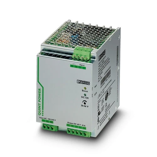
The Phoenix Contact QUINT-PS/1AC/24DC/20 power supply is a high-performance 24 V DC unit designed to deliver 20 A output for demanding automation and industrial applications. It features advanced technology for superior protection, including selective fuse breaking to rapidly disconnect faulty circuits and maintain system stability. With a built-in power boost function, it can provide extra current for starting heavy loads, ensuring smooth operation even under high inrush conditions. Its preventive monitoring capabilities identify potential issues before they become failures, helping to keep systems running efficiently with reduced downtime.
The QUINT-PS/1AC/24DC/20 stands out for its combination of robust design, efficiency, and intelligent diagnostics. Adjustable output voltage and high efficiency reduce energy losses while providing flexibility for varied installation needs. Engineers benefit from increased system availability thanks to early-warning signals that highlight critical operating states. Its compact DIN rail mounting design simplifies integration into control cabinets while offering parallel and series connectivity for redundancy or higher capacity. Whether powering automation equipment, process controllers, or heavy-duty actuators, this power supply ensures consistent performance, extended service life, and dependable operation across a wide range of environments.
The QUINT-PS/1AC/24DC/20 is built for engineers who need reliability, flexibility, and safety in one compact power supply. With its selective fuse breaking, Power Boost reserve, and predictive monitoring, it transforms a standard supply into an intelligent safeguard for industrial systems. It’s not just a power source—it’s a performance enhancer that extends uptime, simplifies integration, and adapts to both heavy loads and sensitive electronics.
Industrial systems often struggle with sudden load peaks, unexpected shutdowns, and hidden failures. The QUINT-PS/1AC/24DC/20 solves these challenges by providing instant current boosts, early-warning diagnostics, and rapid circuit protection. It ensures heavy machines start reliably, sensitive devices remain stable, and critical operations avoid costly downtime. In short, it addresses the weakest link in power reliability and turns it into a strength for your automation setup.
| Feature | Details | Benefit |
|---|---|---|
| Output Voltage / Current | 24 V DC ±1% / 20 A | Delivers stable power for critical automation systems |
| Power Boost Function | Up to 26 A (1.5× rated current) | Ensures reliable start-up of heavy loads |
| SFB Technology | Selective Fuse Breaking up to 6× rated current (12 ms) | Provides rapid protection, prevents downtime |
| Adjustable Voltage Range | 18–29.5 V DC | Flexible adaptation to varied applications |
| Efficiency | Up to 92.7% | Reduces energy loss and heat build-up |
| Preventive Function Monitoring | Reports critical states before failure | Enables predictive maintenance and higher uptime |
| Parallel & Series Connection | Supported | Scalable capacity and redundancy for mission-critical systems |
| Mounting Type | DIN rail (NS 35, EN 60715) | Quick and space-saving cabinet installation |
| Input Voltage Range | 85–264 V AC / 90–350 V DC | Wide compatibility with global supply networks |
| Protection Class | Class I, IP20 | Safe operation and reliable insulation |
| Operating Temperature | -25 °C to +70 °C (with derating >60 °C) | Reliable performance in harsh environments |
| Dimensions (W x H x D) | 90 × 130 × 125 mm | Compact design for tight enclosures |
| Approvals | UL Listed, CSA, SEMI F47, shipbuilding standards | Certified for global industrial applications |
| Weight | 1,608 g (net) | Lightweight yet robust build |
Download Phoenix Contact QUINT-PS/1AC/24DC/20 (2866776) Datasheet
| Commercial Attribute | Details |
|---|---|
| GTIN (EAN/UPC) | 4046356113557 |
| Customs Tariff Number (HS Code) | 85044095 |
| Weight (incl. packing) | 2,230 g |
| Weight (net, excl. packing) | 1,608 g |
| Country of Origin | Thailand (TH) |
In modern assembly lines, maintaining stable power is critical for controllers, servo motors, and robotic arms. The QUINT-PS/1AC/24DC/20 delivers reliable 24 V DC output and its Power Boost function supplies additional current to handle heavy start-ups without interruption. Preventive monitoring provides maintenance teams with early alerts, reducing unplanned shutdowns. By combining fast fuse breaking and intelligent diagnostics, it ensures consistent performance, helping manufacturers maximize throughput and minimize costly production downtime.
For applications in oil and gas facilities, remote pumping stations, or outdoor monitoring units, power equipment must withstand demanding environments. This model operates across a wide temperature range and resists electrical disturbances, ensuring system reliability even in extreme conditions. Its selective fuse breaking feature protects the system by isolating faults instantly, while adjustable voltage capability compensates for long cable runs. These qualities make it a dependable choice for remote or outdoor installations where service access is limited.
In transportation infrastructure, where safety and reliability are non-negotiable, the QUINT-PS/1AC/24DC/20 provides uninterrupted power to control relays, track circuits, and signaling systems. Its rapid fault isolation prevents cascading failures and keeps vital subsystems operational even when overloads occur. Built-in function monitoring adds predictive capabilities, allowing engineers to take corrective measures before problems escalate. This ensures smoother railway operations, safer road crossings, and reliable traffic signal performance under continuous load conditions.
Large facilities rely on centralized systems to manage heating, ventilation, lighting, and security equipment. The QUINT-PS/1AC/24DC/20 provides a stable supply to controllers, surveillance systems, and alarms, preventing disruptions during load variations. Its adjustable output voltage compensates for distance-related drops, ensuring sensitive electronics receive the correct supply. With preventive monitoring and redundancy options, facility managers gain peace of mind that building automation and security networks remain dependable, even during power fluctuations or component wear.
| Category | Model Name | Article No. | Benefit |
|---|---|---|---|
| Redundancy Module | QUINT-DIODE/12-24DC/2X20/1X40 | 2320157 | Provides uniform redundancy up to 40 A, ensuring uninterrupted power to critical loads |
| Active Redundancy Module | QUINT-ORING/24DC/2X20/1X40 | 2320186 | Active redundancy with Auto Current Balancing (ACB) and monitoring for maximum reliability |
| EMC Filter | ME-MAX-NEF/QUINT20A | 2319919 | Ensures compliance with EMC standards, especially in shipbuilding and sensitive environments |
| Circuit Breaker (1A) | CB TM1 1A SFB P | 2800836 | Thermal-magnetic protection with SFB characteristic for system selectivity |
| Circuit Breaker (2A) | CB TM1 2A SFB P | 2800837 | Selective tripping protection for 2 A loads |
| Circuit Breaker (3A) | CB TM1 3A SFB P | 2800838 | Designed for 3 A circuits with fast fault isolation |
| Circuit Breaker (4A) | CB TM1 4A SFB P | 2800839 | Effective overcurrent protection tailored for 4 A devices |
| Circuit Breaker (5A) | CB TM1 5A SFB P | 2800840 | Provides circuit protection and reliability for 5 A branches |
| Circuit Breaker (6A) | CB TM1 6A SFB P | 2800841 | Maintains selective protection in 6 A system designs |
| Circuit Breaker (8A) | CB TM1 8A SFB P | 2800842 | Supports medium loads with precise SFB tripping |
| Circuit Breaker (10A) | CB TM1 10A SFB P | 2800843 | Ensures stable protection for higher current loads |
| Mounting Adapter | UWA 182/52 | 2938235 | Secure wall mounting option for vibration-prone installations |
| DIN Rail Adapter | UTA 107 | 2853983 | Universal DIN rail adapter for flexible installation |
| Cooling Fan | QUINT-PS/FAN/4 | 2320076 | Enhances cooling for continuous operation at higher temperatures |
| Surge Protection Device (230 V) | PLT-SEC-T3-230-FM-UT | 2907919 | Protects against surges in single-phase 230 V networks |
| Surge Protection Device (24 V) | PLT-SEC-T3-24-FM-UT | 2907916 | Surge protection tailored for 24 V networks and automation systems |
For expert guidance before placing your order.
Warranty – 1-year warranty for your peace of mind.
Global Shipping – We ship worldwide with secure packaging and reliable delivery.
Technical Support – Contact us for professional after-sales technical assistance.