USD 370.50
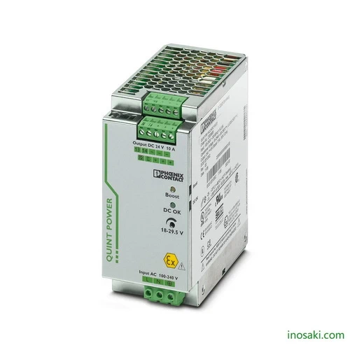
High-reliability Phoenix Contact QUINT-PS/1AC/24DC/10/CO power supply with SFB technology, 24V DC, 10A output, POWER BOOST, and preventive monitoring.
The Phoenix Contact QUINT-PS/1AC/24DC/10/CO power supply is engineered to deliver dependable 24 V DC output at 10 A for demanding automation and control tasks. Its advanced SFB (Selective Fuse Breaking) technology ensures circuit breakers react instantly, protecting critical equipment and minimizing downtime. With a wide adjustable output range from 18 V to 29.5 V DC and preventive monitoring functions, it detects irregular conditions before they cause failures. A protective coating safeguards against humidity and harsh environments, making it ideal for long-term, high-availability operation in industrial, energy, and process applications.
The QUINT-PS/1AC/24DC/10/CO excels where reliability and system continuity are essential. Its POWER BOOST reserve supplies up to 1.5 times the rated current, ensuring smooth startup for heavy loads such as motors or automation drives without oversizing. Real-world benefits include fewer interruptions, greater equipment protection, and extended system life. Preventive diagnostics allow maintenance teams to take action before downtime occurs, reducing costs and boosting productivity. Built with international approvals and a rugged design, it performs consistently even in challenging industrial or transportation environments, ensuring stable power for mission-critical processes.
The Phoenix Contact QUINT-PS/1AC/24DC/10/CO is more than just a power supply—it’s a safeguard for your entire automation system. Its unique combination of POWER BOOST and SFB technology ensures that even the toughest loads start reliably and that fuses trip instantly when needed. Preventive monitoring gives operators an early warning, helping to avoid costly failures. Designed with a protective coating for harsh conditions, it provides unmatched durability and performance where uptime is non-negotiable.
In industrial environments, power fluctuations and overloads can bring entire systems to a halt. The QUINT-PS/1AC/24DC/10/CO solves this by ensuring stable 24 V DC output, quick fault isolation, and reliable startup of high-demand loads. Instead of unexpected downtime, users gain proactive system protection and continuous operation. Whether in factory automation, process control, or transportation, it eliminates weak links in the power chain, keeping production efficient, safe, and uninterrupted.
| Feature | Details | Benefit |
|---|---|---|
| Output Voltage | 24 V DC (adjustable 18…29.5 V DC) | Flexible power range for diverse industrial applications |
| Output Current | 10 A nominal | Stable and reliable supply for medium to heavy loads |
| POWER BOOST | Up to 15 A (1.5x rated current) | Ensures reliable startup of demanding loads without oversizing |
| SFB Technology | Up to 6x nominal current for 12 ms | Enables fast tripping of standard circuit breakers for superior protection |
| Preventive Monitoring | Real-time status and early warnings | Detects issues before failures occur, reducing downtime |
| Protective Coating | Conformal coating for 100% humidity | Long-term durability in harsh or humid environments |
| Efficiency | Up to 93.2% | Lower energy loss, improved system efficiency |
| Input Voltage Range | 85…264 V AC / 90…350 V DC | Wide operating range for global compatibility |
| Mounting | DIN rail, screw connection | Easy and secure installation in control cabinets |
| Approvals | UL, ATEX, IECEx, DNV GL, SEMI F47 | Certified for global industrial and transportation use |
| Dimensions (W x H x D) | 60 x 130 x 125 mm | Compact footprint, saves panel space |
| Operating Temp. | -40 °C … +70 °C (derating > 60 °C) | Reliable in extreme conditions |
| System Integration | Parallel and series connection supported | Scalable for redundancy or higher power needs |
Download Phoenix Contact QUINT-PS/1AC/24DC/10/CO (2320911) Datasheet
| Commercial Attribute | Details |
|---|---|
| GTIN (EAN/UPC) | 4046356520027 |
| Customs Tariff Number (HS Code) | 85044095 |
| Weight (incl. packing) | 1,544.5 g |
| Weight (net, excl. packing) | 1,145 g |
| Country of Origin | Thailand (TH) |
Modern packaging lines use conveyors, actuators, and robotics that often draw high inrush currents during startup. The POWER BOOST reserve ensures motors and drives start without hesitation, eliminating the need for oversizing equipment. At the same time, the selective fuse breaking function quickly isolates faults, so only the affected circuit shuts down while the rest of the system continues running. This balance of power reserve and fault control keeps packaging lines efficient and reduces costly stoppages.
In production plants, control cabinets house PLCs, sensors, and data interfaces that must remain stable under varying load conditions. The preventive function monitoring continuously checks system status, alerting maintenance teams early if voltage or load irregularities occur. Combined with its protective coating against humidity and dust, the unit delivers dependable power for sensitive devices, cutting unplanned downtime and extending equipment life in demanding factory settings.
Railway signaling infrastructure depends on uninterrupted 24 V power, even under fluctuating supply conditions. The rapid fault isolation capability ensures that individual failures do not disrupt the entire network. Extended buffering time maintains operation during short mains interruptions, while diagnostic signals allow technicians to take corrective action before failures impact service. This reliability is vital for ensuring passenger safety and consistent railway operations in all weather conditions.
Solar and wind energy facilities require stable DC power for inverters, monitoring devices, and communication equipment. The adjustable voltage range allows the supply to adapt to different components, while its high efficiency minimizes energy losses in remote installations. With overload protection and a rugged design, it ensures clean power delivery in harsh environments. This makes it an excellent fit for renewable energy projects where reliability and long-term performance are critical.
| Category | Model / Accessory | Article No. | Benefit |
|---|---|---|---|
| Mounting Adapter | UTA 107 – DIN rail adapter | 2853983 | Enables secure mounting on universal DIN rails |
| Mounting Adapter | UWA 182/52 – Wall adapter | 2938235 | Ensures safe installation on walls or surfaces exposed to vibration |
| Mounting Adapter | QUINT-PS-ADAPTERS7/2 | 2938206 | Allows direct assembly of QUINT POWER 10 A onto Siemens S7-300 rails |
| Cooling Accessory | QUINT-PS/FAN/4 | 2320076 | Provides additional cooling for higher ambient temperatures or rotated installation |
| Redundancy Module | QUINT-DIODE/12-24DC/2X20/1X40 | 2320157 | Ensures uniform redundancy and reliable supply up to the consumer |
| Redundancy Module | QUINT-ORING/24DC/2X10/1X20 (with coating) | 2320173 | Active redundancy with Auto Current Balancing (ACB) and monitoring functions |
| Redundancy Module | TRIO-DIODE/12-24DC/2X10/1X20 | 2866514 | Compact redundancy option with function monitoring |
| Circuit Breaker | CB TM1 1A SFB P | 2800836 | Thermal-magnetic breaker designed for SFB technology |
| Circuit Breaker | CB TM1 2A SFB P | 2800837 | Provides selective protection for smaller loads |
| Circuit Breaker | CB TM1 3A SFB P | 2800838 | Reliable circuit isolation for medium loads |
| Circuit Breaker | CB TM1 4A SFB P | 2800839 | Matches SFB tripping for system-level protection |
| Circuit Breaker | CB TM1 5A SFB P | 2800840 | Handles higher loads with fast-acting protection |
| Surge Protection | PLT-SEC-T3-230-FM-UT | 2907919 | Protects single-phase AC supply networks against surges |
| Surge Protection | PLT-SEC-T3-24-FM-UT | 2907916 | Safeguards 24 V DC supply lines from transient surges |
For expert guidance before placing your order.
Warranty – 1-year warranty for your peace of mind.
Global Shipping – We ship worldwide with secure packaging and reliable delivery.
Technical Support – Contact us for professional after-sales technical assistance.