USD 480.74
Reliable Phoenix Contact QUINT-PS/1AC/12DC/20 power supply, 12V DC 20A output with SFB Technology, POWER BOOST, and preventive monitoring for industrial use.
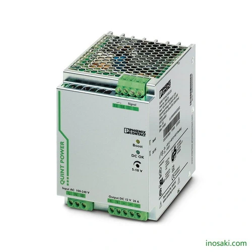
The Phoenix Contact QUINT-PS/1AC/12DC/20 is a high-performance industrial power supply that delivers 12 V DC at 20 A, built to ensure maximum reliability in demanding environments. With its advanced Selective Fuse Breaking (SFB) function, it trips standard circuit breakers quickly, enhancing system protection and minimizing downtime. The integrated POWER BOOST reserve provides extra current for starting heavy loads, while the adjustable output range (5–18 V DC) allows flexible use across various applications. Combining efficiency, robust construction, and early warning monitoring, this model is ideal for automation systems, machinery, and safety-critical operations.
Engineered for long-term reliability, the QUINT-PS/1AC/12DC/20 power supply goes beyond delivering power by actively protecting your system. Its preventive monitoring alerts operators before faults escalate, reducing costly interruptions. The static POWER BOOST feature ensures that motors and other demanding devices can start without hesitation, while its efficiency rating above 90% keeps energy consumption low and heat generation minimal. Compact in size and built with IP20-rated durability, it integrates seamlessly into control cabinets. This makes it a trusted solution for industries such as manufacturing, process control, and transport systems where consistent performance is essential.
The Phoenix Contact QUINT-PS/1AC/12DC/20 is more than a power supply—it’s a safeguard for your entire automation system. With SFB Technology for rapid fuse tripping, POWER BOOST for heavy load start-up, and preventive monitoring that detects issues before they become failures, it ensures maximum uptime. Designed for flexibility, reliability, and energy efficiency, it supports industries where uninterrupted power and operational safety are critical.
Unstable power and sudden load demands often cause downtime, equipment failure, and costly repairs. The QUINT-PS/1AC/12DC/20 eliminates these risks by delivering consistent 12 V DC / 20 A output with reserve power for peak demands. Its fast response protects circuits before damage occurs, while predictive monitoring helps maintenance teams act proactively. In industrial automation, transport, and manufacturing, it solves the challenge of maintaining continuous, stable, and safe power under tough conditions.
| Feature | Details | Benefit |
|---|---|---|
| Nominal Output Voltage | 12 V DC ±1% | Provides stable power for sensitive industrial electronics. |
| Output Current | 20 A continuous (POWER BOOST up to 26 A) | Ensures reliable startup of heavy or high inrush loads. |
| Voltage Adjustment Range | 5 V DC … 18 V DC | Flexible adaptation for different applications and devices. |
| Output Power | 240 W | Supports demanding systems with high energy needs. |
| Efficiency | > 90% at 230 V AC | Reduces energy loss and minimizes heat for longer component life. |
| SFB Technology | Selective Fuse Breaking, 6x nominal current | Enables fast circuit breaker tripping for maximum system protection. |
| Preventive Function Monitoring | Reports critical states early | Minimizes downtime with predictive maintenance alerts. |
| Input Voltage Range | 100 … 240 V AC (85 … 264 V AC), 90 … 350 V DC | Wide operating range supports global use. |
| Overvoltage Protection | < 25 V DC | Protects connected equipment from voltage spikes. |
| Parallel/Series Connection | Yes, supported | Allows redundancy or higher capacity configurations. |
| Inrush Current | < 20 A | Prevents overload during startup. |
| Ambient Temperature Range | -25 °C … +70 °C (derating above 60 °C) | Reliable operation in harsh industrial environments. |
| MTBF (IEC 61709) | > 1,000,000 h at 25 °C | Long service life ensures reduced replacement costs. |
| Protection Class | IP20 | Safe integration inside control cabinets. |
| Dimensions (W x H x D) | 90 x 130 x 125 mm | Compact design for space-saving installation. |
| Weight (net) | 1.5 kg | Easy to handle and install in industrial panels. |
| Certifications | UL 508, CSA, SEMI F47, IEC 60601-1 | Approved for global use, including medical and hazardous environments. |
Download Phoenix Contact QUINT-PS/1AC/12DC/20 (2866721) Datasheet
| Commercial Attribute | Details |
|---|---|
| GTIN (EAN/UPC) | 4046356113564 |
| Customs Tariff Number (HS Code) | 85044095 |
| Weight (incl. packing) | 2,045 g |
| Weight (net, excl. packing) | 1,500 g |
| Country of Origin | Thailand (TH) |
Automation systems rely on stable power for PLCs, sensors, and actuators. The QUINT-PS/1AC/12DC/20 ensures continuous performance with a strong 20 A output and added reserve capacity for sudden current surges. Its rapid fuse-breaking function isolates only the faulty branch, so the rest of the control system keeps running. This makes it a reliable choice for complex cabinets where even short interruptions can cause costly downtime.
Many installations must operate under demanding conditions such as extreme temperatures, vibration, or electrical noise. With a wide operating range from –25 °C to +70 °C, the QUINT-PS maintains a steady power output despite environmental stress. Its rugged metal housing and preventive monitoring features further support uninterrupted operation, giving operators confidence that vital equipment will continue running in tough locations like transport systems, outdoor panels, or industrial sites.
Critical facilities including telecommunications, data processing, and public services cannot afford unexpected shutdowns. The QUINT-PS/1AC/12DC/20 supports parallel operation, making it suitable for redundancy concepts where one unit can instantly take over if another fails. Early diagnostic signaling alerts maintenance teams before issues escalate, while fast fuse tripping prevents wider system disturbances. This ensures maximum availability for applications where continuity of service is essential.
Robotic arms, packaging lines, and high-speed machinery often demand high current at startup. The integrated POWER BOOST feature provides extra energy exactly when needed, preventing voltage drops that can disrupt equipment. Combined with selective fuse technology, the QUINT-PS protects other circuits from overloads and enables machines to start smoothly every time. This results in higher productivity, fewer unexpected stoppages, and lower long-term maintenance costs.
| Category | Model Name | Article Number | Benefit |
|---|---|---|---|
| DIN Rail Adapter | UTA 107 | 2853983 | Enables secure DIN rail mounting for flexible installation. |
| Wall Mount Adapter | UWA 182/52 | 2938235 | Provides stable wall installation in environments with vibration. |
| Redundancy Module | QUINT-DIODE/12-24DC/2X20/1X40 | 2320157 | Ensures uniform load sharing and power redundancy for critical systems. |
| Redundancy Module | TRIO-DIODE/12-24DC/2X10/1X20 | 2866514 | Adds monitoring and redundancy to protect connected loads. |
| Circuit Breaker (1 A) | CB TM1 1A SFB P | 2800836 | Provides selective protection with SFB tripping characteristics. |
| Circuit Breaker (2 A) | CB TM1 2A SFB P | 2800837 | Reliable protection for low current circuits with plug-in convenience. |
| Circuit Breaker (3 A) | CB TM1 3A SFB P | 2800838 | Prevents overload in smaller circuits with SFB protection. |
| Circuit Breaker (4 A) | CB TM1 4A SFB P | 2800839 | Ideal for protecting medium-load branches in automation panels. |
| Circuit Breaker (5 A) | CB TM1 5A SFB P | 2800840 | Protects downstream equipment while supporting SFB technology. |
| Surge Protection Device | PLT-SEC-T3-230-FM-UT | 2907919 | Safeguards power supply against surge voltages in 230 V systems. |
For expert guidance before placing your order.
Warranty – 1-year warranty for your peace of mind.
Global Shipping – We ship worldwide with secure packaging and reliable delivery.
Technical Support – Contact us for professional after-sales technical assistance.